Bent Valves or No?

Yamaha FJR Motorcycle Forum

Help Support Yamaha FJR Motorcycle Forum:

This site may earn a commission from merchant affiliate links, including eBay, Amazon, and others.

hppants

Well-known member
Joined
Aug 5, 2011
Messages
2,942
Reaction score
2,670
Location
Lafayette, LA
Helped MikeP1300 check his valves this morning. All were in spec, but a few were close to tight spec (both intake and exhaust). We decided to shim them to the loose side of spec all around, hoping to follow Fred's lead and not have to worry about it for a while.

Mistake #1 - we did NOT put the crank on TDC before starting.

We ziptied both cams to the chain, and ziptied the rotor sensor wheel to the chain as well. Loosened the cam chain and started with the intake. moved the cam over - pulled shims, put back together - all good. One of the intakes (I believe it was #2) had the lobes down. So we had to work against the valves to put the cam on, but it went without trouble.

Pulled the exhaust and the same thing happened.

Mistake #2 - upon trying to reinstall the exhaust cam, lobes on #4 are down, so we rotated the crank slightly to get it to fall in place. Tightened everything down and released the CCT. Untied the zips all around. Now I can't turn the crank a full turn using a rachet on the bolt without hitting something hard.

Oh **** - big mistake #3.

Long story short, we spent the entire afternoon trying to line up the cams and the crank in time. We followed the book except for one thing. The arrows on the cam gears are on the outer side. With the motor in the frame, we can't put our eyes on the arrows. So we pulled the cams and transferred a pencil mark on the inside of the cam gear.

Funny thing about this. On the exhaust side, when the marks are lined up with the cylinder head, the #4 outer cam lobe has the hole at straight up. However, on the intake side, we cannot rotate the camshaft such that the marks are lined up AND the hole is straight up. There are two possibilities for where the cam can be placed. One way, or 180 degress the opposite. On one way, the right most cam lobe is straight up. At 180 degrees opposite, the hole is at about 45 degrees from straight up.

So I put the crank on TDC (with the cams out) and removed the rotor sensor. I then slid the cam chain off the crank gear. We lined up both cams and put the chain on it as tight as we could get between the cam gears. I then moved the chain forward and backward a tooth such that the crank remained on TDC, and both cams lined up with their marks. We then tighten down the camshafts while I held the cam chain in place on the crank gear. After everything is tightened down, the crank has moved about 10 degrees (missed a tooth or two). Again, I can't turn the crank more than about 150 degrees in either direction before I hit a stop.

We tried to repeat with no luck. So on Monday, the bike is going to the dealer.

So.... my biggest questions are:

1. When the crank is at TDC, and the cams are lined up correctly (arrows on the head), do the lobe holes on both the exhaust and intake run straight up and down?

2. When the crank is at TDS, and the cams are lined up correctly, are all of the lobes (intake and exhaust) away from the bottom - that is, are ALL 16 valves supposed to be fully closed at that time?

3. If I pushed one (or more) valves against the top of a piston while trying to set the timing, could I have bent the valve using only the force of 2 or 4 of the cam bearing cap bolts? Or more likely did the valve just push the piston down and rotate the crank (which is probably why my TDC mark didn't line up)?

At this point, it's time to pour money on it.

I feel horrible for Mike. I tried to help him and of course I made matters worse.

I think I'm just about done turning wrenches on motorcycles.

 
Last edited by a moderator:
I'm trying not to be confused...... but...... I am not sure where the "holes" line up. To me nothing matters but timing marks.

With crank at TDC and the camshaft sprocket timing marks lined up with the top edge of the cylinder head (gunsight with strong flashlight), I believe the #1 cylinder is at TDC, with camshaft lobes pointed outward as shown in the FSM (provided you had not done anything yet). It is irrelevant where the cam lobes are on any other cylinder, as they will be "in time" with their relative piston positions. However, I see the possibility by your description where you may have had the cams rotated incorrectly, and if you bolted the cams down, if that cam wanted the valve to be open and if the piston was up, there MAY be a bent valve........ I don't know if you met a lot of resistance bolting the cam down (if so, lucky you didn't break a cam), but it would be more likely to bend a valve IF you tried to overcome that resistance you felt when you rotated the crank........... how much bend... how hard did you crank on it....... I don't wanna know.

Anyhow, back to square one....... give it one more shot........ if you have #1 piston verified at TDC, camshaft timing marks lined up, verify cam lobes look like the FSM, CCT extended, one should normally be able to spin the motor over without an issue. IF a valve is bent and sticking in the open position, then yep, you've got a problem.........

Another way to verify this....... all cams out, all valve buckets should be at relatively the same level if all the valve springs were able to do their job, as all valves will be closed. If you find one that is sitting down, there's your bent valve... it wasn't able to go back in the guide due to the bend, or the valve head was bent off kilter. What I don't know is how much clearance does a valve have to the piston normally......

Yet another verification while you have all the cams out, and perhaps can't tell if one was bent or not, do a leakdown test (compressed air into the spark plug hole).... if leaky, valve is not seated. Fingers crossed.

 
Last edited by a moderator:
Raz - Thanks for the detailed reply. First, I didn't try to force the crank to turn once I found resistance. With the motor together, I simply rotated the crank clockwise with my rachet - maybe exhibiting 10 ft # of touque and when the crank stopped, so did I. So if I bent a valve(s), I don't think I did it with the rachet on the crank bolt.

Another question - if the cam chain and the cams are not assembled in the motor (all valves closed), does it matter how many times I have to rotate the crank to find #1 TDC? IOW - when the "t" mark is lined up with the split in the case halves, #1 should be on TDC EVERY revolution?

Also, when #1 is at TDC, are any other holes also at TDC?

Thanks for the clarification regarding the cam lobe holes. We basically abandoned looking at those and used the timing marks on the cylinder head to line up our cams. While mike was doing that, I was trying to hold the cam chain on the crank gear where I thought it would be lined up and still hold the crank at TDC. In both cases, after the cams were tightened down, the crank was out of position (about 10 degrees).

So what I think is happening is that I do not have my cam timing correct, and the lobe(s) that are out of time are pushing the valves open. Whichever valve is closest to the #1 piston (and/or any other piston that is at TDC), those valves are moving the piston such that the crank is now also out of time.

What I don't know is if that is enough to bend valves or not.

I can say that when the cams are out of the head, all valves look to be the same - if one is not seating correctly, it's not by much. Of course, I know that it doesn't have to be much.

 
I am just hoping you don't have a bent valve, but it's not certain at this point.

Since you can't rotate the engine, remove the camshafts. Are the buckets even? If not, proceed with caution when rotating engine. Hang cam chain so you don't lose it, ensure it is not hanging up down below. Rotate the engine 360 degrees clockwise, if you encounter resistance and it's not the cam chain at the crank end, could be hitting a valve. You can put a long screwdriver or wire in the spark plug holes, two cylinders will be up, two will be down. 1&4 and 2&3 go up/down together. If you had resistance, of course it is one of the cylinders that is up.

If your rotation went well, time to install the camshafts in the correct location. Follow the FSM in the engine section (5-12 etc.). We do want the ignition to fire when that particular cylinder is on compression stroke.

Rotate the crank until #1 is TDC, and ignition timing wheel at crank end is in correct position (should be). Keep it there while you install the cams in the correct orientation.

If you had bad news on your rotation, I would do a leakdown test. A bent valve will be very obvious as the leak will be significant pissing of air. Now, since you rotated the crank both directions during your initial adventure, there may be more than one valve affected. But, let's see what you find first before we speculate.

 
Last edited by a moderator:
Pants, the cylinders work in pairs, as RaYzerman stated. 1 & 4 move together, and 2 & 3 move together. If 1 is at TDC, so is 4. With the cams not installed, it does not matter if that TDC is compression or exhaust stroke. That difference is valves, not crankshaft position, so if the cams are out, that difference doesn't exist. (I've actually had to drill that into some heads when I've helped them.)

When you install the cams, you actually "lead" the timing, because when the chain tensioner goes tight there will be a position shift in the cams. That could be why you found the timing off when you tightened the cam caps, but 10 degrees? I dunno......

Make sure you're referring to the cylinder numbers correctly. The cam sprockets are at the #4 end. I've seen people try to match the cam lobe direction shown in the service manual to the lobes closest to the sprockets, which is wrong. The manual shows the timing mark positions and the #1 lobe positions (just as a check,) which are at the far end of the cam. I'm just putting that out there to make sure, I have no reason to think that's news to you. With #1 at TDC and the cam timing correct, the lobes at #1 are splayed outward.

 
Yep, I think wfooshee and I are trying to say the same thing...... the engine doesn't care if it is on compression or exhaust stroke with no cams. Hopefully if you spin it then, you find no issues. Putting the cams back in with the timing marks oriented correctly now makes #1 on compression stroke. I was only concerned that one cam isn't 180 degrees out, that's why follow the FSM for orientation. Again, fingers crossed.

 
1. When the crank is at TDC, and the cams are lined up correctly (arrows on the head), do the lobe holes on both the exhaust and intake run straight up and down?
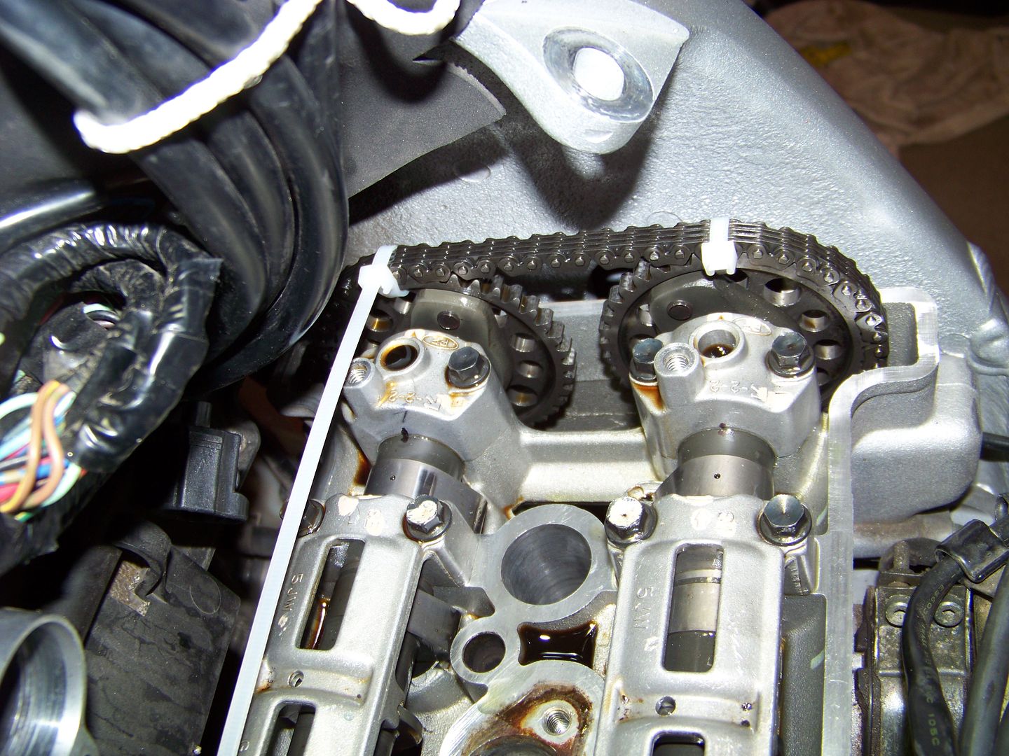
Yes. See photo below. When at #1 TDC the two holes in the back side of the right #4 cams both face straight up to the arrows cast in the cam caps. These are also alignment marks and a lot easier to see than the marks on the right end of the cam sprockets. You can see in the photo that before I loosened the chain, I took a sharpie marker and made match marks on the right most cam caps and the cam shafts to further ensure it was all back to correct timing.

100_3802.jpg


OK - this is most helpful. I'm sorry for the long post, but I want to describe my thoughts as accurately as I can. I don't want you to assume anything from context. If I were you, I'd wonder if Pants knows the difference between a wrench and a socket, let alone have this conversation.

1. We are all discussing the correct firing order #1 closest to left turn signal. Also, if I understand you correctly, we should be able to remove the camshafts, remove the chain from the crank gear, and hold the chain from above to keep it from falling. From that point, if we can rotate the crank freely by hand without hitting anything, chances are we have not bent any valves. We can also examine the shim buckets across the board and see if any one of them sits lower than the others. Admittedly, I don't know how we could ACCURATELY measure this - a valve bent 0.010" is still a bent valve. But I'm told that this is a true interference motor and if that is the case, a valve bent 0.010" should knock the piston when the crank is turned by hand - yes?

2. A programming note: we did not remove the cam gears from the camshafts. Also, the cam gear alignment marks are on the outside face of the gears. On the intake side, we can see the alignment mark by looking (steep angle) between the motor and the frame. However, on the exhaust side, we simply cannot. Therefore, we transferred our alignment marks with a pencil on the inside of the cam gears. We fully recognize that our transferred mark might be a few thousands of an inch off, but considering the number of teeth on the cam gears, we figured that it should be close enough. If that assumption is wrong, then somebody has to pull the motor out for us to continue- yes?

3. My "10 degree" was an estimate, it might have been less, but for sure the "T" mark on the crank was past (in a clockwise direction) the split in the cases when the camshafts were timed up top.

4. If #1 and #4 are at TDC at the same time, it would stand to reason that when the camshafts are timed correctly, the #1 and #4 cam lobes (both intake and exhaust) should be oriented anywhere EXCEPT down, yes? IF these lobes were down, then they would be trying to open valves on an interference motor with the piston at the top of the stroke - I don't think that will work.

5. I'm trying to follow the FSM (Chilton's) for the cam orientation. It does make sense that the cam marks can be lined up and be 180 degrees out of time. The FSM says that when the cams are in the correct position, the marks are lined up and there will be a "hole on the lobe closest to the cam gear (#4 right most cam lobe) pointing "up". I don't know if I should interpret the word "up" literally or relatively.

For the exhaust cam, the "hole" referred to is about 180 degrees opposite of the peak of the cam lobe. I can line up the timing marks and the lobe hole is straight up top. Here's the rub: If #4 is at TDC, and the #4 exhaust lobes are straight down, that would mean that when I tighten up the camshaft, I will be pushing those exhaust valves open and with the piston on TDC, we will have a problem.

For the intake cam, I have a different concern. The "hole" on the rightmost lobe closest to the cam gear about 90 degrees off of the peak of the cam lobe - not exactly 90 degrees but close. And it is in that position when the timing marks are lined up. On one timing mark alignment, the hole is more to toward the top, and on the other, it's more toward the bottom.

6. Would anybody know which direction I should be "leading" the cams? Rotate toward the intake side a smidge (counterclockwise looking at the gear from the right side of the motor) or rotate toward the exhaust side a smidge (clockwise)? Also, how much lead? 1 tooth? 1/2 tooth?

We buttoned the bike back together and are planning to take it to the dealer. I'm not opposed to taking it back apart and trying again. It will only cost us time and from what I'm reading here, if we bent valve(s), we can't break it anymore than it's broke. OTOH - if I go back into it with more knowledge, I may be able to put it back right.

Regardless - I really appreciate all of the help.

 
Last edited by a moderator:
I wish we had not put it back together - I could have confirmed my thoughts with pictures.

My recollection was that on the intake side, we did NOT have what Fred describes. It would have been a great idea for me to take a sharpie and mark our holes like Fred did. Hindsight is clearer....

Edit - Fred, when your motor was orientated for the picture above, did you confirm that the cam gear timing marks were lined up with the top of the cylinder head? Or did you just confirm the crank at TDS ("T" mark)?

RFH - sage advice. A parts changer should not be doing this kind of work. I'm very upset with myself. I do take some comfort in the fact that no one got hurt and the rest is just metal and money. But I'm pissed off at myself for thinking I could do this **** in the first place. On my Gen 1, I checked valves twice, but never attempted to replace a shim. HUGE difference.

One way or the other, it will work out.

 
Last edited by a moderator:
4. Ignore #4 cam lobes, concentrate on #1 only..... everything else will fall into place. If #1 at TDC and #1 cams splayed out per FSM, #4 lobes might be pointing inboard, but who cares. As long as #1 is TDC, lobes splayed correctly, timing marks on end of cam sprockets lined up with edge of cylinder head, valve timing will be correct.

5. Using the lobe holes (per Fred's pic) is a way to indicate you are there. If you are off a tad, you could be one tooth out, and to me, the only way to prevent that or verify that is to check the end of the cam sprockets...... it is hard to gunsight, but sit on a stool with your head still and a strong flashlight, I don't find it too awful to do. It helps to highlight the marks with white grease pencil or a dab of paint.

6. With everything in place, there should be no slack along the forward part of the cam chain... Recheck everything once you have released the CCT, and before you rotate the engine (cam timing marks, crank TDC timing, backup verification of lobe holes, etc.).

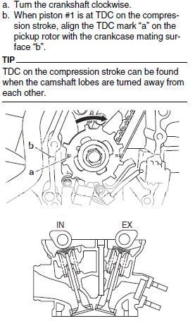
Valve check instruction will help you...... see pic.

FJR%20Valves%201%20TDC_zpsutsyengh.jpg


Last edited by a moderator:
Why ignore the #4 cams? They are directly tied to the rest of the cams on that shaft.

You can see in my photo what the #4 cams look like when the #1 is at TDC and its two cams are pointing upward and splayed out (as in the line drawing from the factory service manual directly above). The #4 cams are pointing downward and splayed equally inward, as in my photo.

note: the #4 cams are 180 degrees opposite of #1's on each cam shaft, so they can't be anywhere else when #1 is correct.

 
Last edited by a moderator:
This is helping me understand a lot.

Raz - I'm assuming your FSM is the Yamaha book? It is far different from the Chilton's FSM.

Considering Raz's picture, would it be safe to assume that Fred's picture was taken when his #1 and #4 pistons were at the end of the exhaust stroke (as opposed to compression)?

Also, once this is all together, how do I torque the crank bolt? Maybe put it in 5th gear, off center stand, bitt the front of the bike against a wall, and pushing the rear brake?

 
The diagram from the manual (Ray's) is showing the lobes of #1 and Fred's picture is showing #4. Both #1 and #4 are at TDC but lobes are opposite.

 
So it would appear that the crankshaft turns exactly twice for every time the cams turn once?

Edit - of course it does. It's a four stroke motor. *******, Pants......

 
Last edited by a moderator:
Why ignore the #4 cams? They are directly tied to the rest of the cams on that shaft.
Because the lobe orientation specified in the FSM is for the #1 cams. Being aware that the #4 lobes are 180 degrees from that is fine, but you have to know that, and it's not specified in the manual.

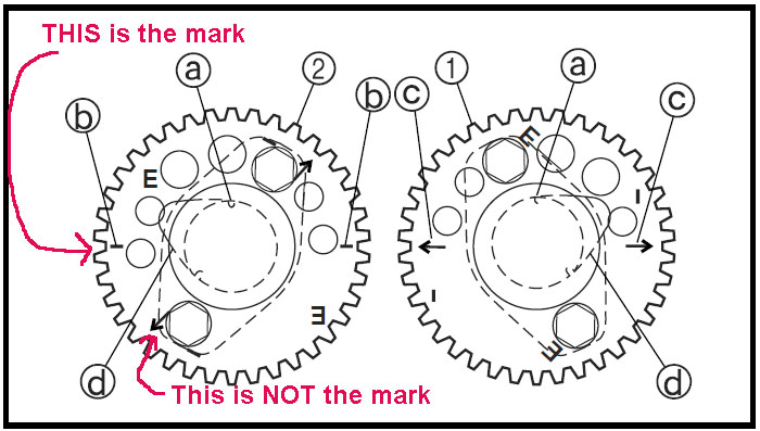
Pants, another thing to consider, be sure you're using the correct timing marks on the intake cam (the one you say you can see.) If you use the mark with the arrow, the cam will be about 45 degrees off and you would be trying to open the #4 valves at TDC.

The timing marks for the intake cam do not have the arrow.

Cam%2Bsprockets.jpg


As for the "leading" the timing that I mentioned earlier, the manual simply says to keep the forward side of the chain as tight as possible when installing the cams. The tensioner will pull the cams backwards relative to the crankshaft if the forward side of the chain has any slack at all. I've seen guys say that they leave that side of the chain just a touch loose and put the cams in a tooth ahead (a tooth clockwise from "correct") to leave room for that when the tensioner comes in. It's quite difficult to judge the chain to be tight on that side when you haven't even got the cams in, yet.

 
Last edited by a moderator:
Oh **** - bingo!!! We have a winner. I'm almost certain we were using the marks with the arrow for both the intake and exhaust.

Confirming, the EXHAUST cam gear marks are the ones with the arrow. The INTAKE cam gear marks are the ones without the arrow?

 
^^^

Diagram and description are on the money! From the pictures in the FSM, it is not 100% obvious that the outlined cam lobe is #1, not #4.

I never had my cams out completely; just moved aside. I was not aware that you used different index marks for intake vs exhaust. Never had a problem because, like Fred, I zip tied the cam sprockets to the chain.

 
Oh **** - bingo!!! We have a winner. I'm almost certain we were using the marks with the arrow for both the intake and exhaust.
Confirming, the EXHAUST cam gear marks are the ones with the arrow. The INTAKE cam gear marks are the ones without the arrow?
Yep

Also remember that the lobe positions for intake and exhaust cams are mirror images to each other.


Latest posts

Top