'Unauthorized' TB synch

Yamaha FJR Motorcycle Forum

Help Support Yamaha FJR Motorcycle Forum:

This site may earn a commission from merchant affiliate links, including eBay, Amazon, and others.

ELP_JC

Well-known member
Joined
Jun 10, 2007
Messages
670
Reaction score
1
Location
El Paso, TX
Okay gang. First of all, a question for the highly technical folks:

Why the heck does Yamaha allow the air screws to be messed with, but not the TB plates??? All my FI bikes have been the opposite: air screws sealed, but we could mess with the throttle plates.

Now back to the 'weird' FJR < he he>.

When I open up my bike for the synch, I want to finish the job right there, so I'm anticipating to the potential need to mess with the plates. And have a few questions before jumping straight to the plate subject.

How far on the rpm range do air screws affect the synch? In other words, above what rpms do we need to synch with the plate screws and not the air screws?

Let's go to the subject now, and am going to do it in the form of questions:

- What threshold are we looking at to decide if we need to synch the TB plates or not? The same 10mmHg as the air screws? Less? More? State what you think.

- Which is the 'base' TB on the FJR? Unlike air screws, there HAS to be one base TB. My guess is #3, just because it's the 'base' recommended for the vacuum check. And what should be done about the blue paint? Redo it, or remove it from all 4 screws? Anything better than broken paint, no? I already removed all visible blue paint from my bike; probably a pound.

-What's the best rpm to synch for the TB plates? 3K? 3.5K? 4K? The higher the rpm, the hotter the engine, which is a problem now for me, with 80º+ lows and triple digit highs, even with a fan... which I don't have.

- This is more like a statement: If we synch the TB plates, we NEED to go back to the air screws, especially if #3 was adjusted, so all TBs are at 250mmHg at idle; this IS a spec we're sure of.

Now the question: Should we check the TB plate synch back again? Just curious.

Finally, I read a ridiculous procedure (no offense to the writer) that had my head spinning before even finishing it. This stuff is not even covered in the service manual, so don't know where it came from. Anyway, I've done tons of synch jobs on my previous bikes, and it simply was a matter of adjusting the 3 adjustable TBs against the fixed one, and you were done. Yes, you had to fiddle a bit with the screws, as sometimes one affects the other, but most of us figure that out in minutes, and end up synching our machines way better than spec.

Or is there anything that makes this bike different than the others?? If so, please explain.

Again, I don't plan to fiddle with this unless I think the synch is bad enough at high rpms that warrants adjustment. On the other hand, it's not a big deal. Or it shouldn't be. Let's see what transpires from this thread. And it'd be great if it could be incorporated to the 'bin of facts' where other folks have access to it.

So have at it gentlemen. Let the controversy begin :yahoo: .

JC

 
Last edited by a moderator:
Okay gang. First of all, a question for the highly technical folks:Why the heck does Yamaha allow the air screws to be messed with, but not the TB plates??? All my FI bikes have been the opposite: air screws sealed, but we could mess with the throttle plates.

<SNIP>

JC
JC, first off U might want to read

https://www.fjrtech.com/getdbitem.cfm?item=21

Then, "The Unauthorized Throttle Body Synchronization Procedure" was posted on the "Other Board" by Amain on 10/21/04. I printed it out and saved it in my FJR book (U do have an FJR book don't U just in case some of this good stuff goes out of print (read, dropped from the queue). I just tried a search for this & couldn't find it-surprising since it's only been almost 3 years. This "Unauthorized" procedure explained how to adjust the throttle body plates at the RPMs we normally ride.

Then someone else posted (and I kick my butt for not printing it out but it is easy to remember) and enhancement to "The Unauthorized Throttle Body Synchronization Procedure" which took in account that, while riding and under load, the throttle plates are opened far more than they are at the same RPMs when the bike is on the center stand in the shop. That being said, this poster suggested that we could disconnect the outside (or inside) two injectors while doing the "The Unauthorized Throttle Body Synchronization Procedure" and this would simulate a load and would have to make the amount of throttle plate opening closer to what it is under load. The poster noted that it makes no difference to the 4 vacuum ports if there is fuel going thru the throttle bodies or not. The poster did say that it will start & run fine on 2 cylinders but would stall if you let it drop down to normal idle.

My ’04 FJR runs so smooth that I only did the 600mi synch but sooner or later I’ll get around to the complete "Unauthorized Throttle Body Synchronization Procedure"

Later,,, De

:rolleyes:

 
Okay gang. First of all, a question for the highly technical folks:Why the heck does Yamaha allow the air screws to be messed with, but not the TB plates??? All my FI bikes have been the opposite: air screws sealed, but we could mess with the throttle plates.
You aren't alone in thinking this. On some bikes, carb bikes included, you have to drill out a cap to get at an air screw if they have one. Triumphs for sure, you change the plate too. My guess is that the way the ECU senses fuel air mixture must be different.

 
First off U might want to read this
I read the service manual's procedure, which is basically the same one outlined in that link. But thanks for posting it, as other folks might benefit.

I'm assuming everybody reading this already knows how to do this, as it's called for in the manual.

As far as that 'unauthorized' procedure you're talking about, I stumbled upon it somewhere during my many weeks of reading, but it was ridiculously complex, and that was one of the reasons I started this thread. And one such reason is there's no need to 'load' the engine; never heard of this before. In fact, error is greater the more closed the plates are (but off their idle stops), so it's more desirable to adjust as low an opening as possible, but since lower rpms have bigger vacuum pulses, you want to raise rpms enough that the pulses allow you more accurately adjust the synch. Each engine has it's 'sweet spot', and I wanted to know which is it on the FJR. Yes, you can find this out yourself by playing with your motor, but at triple digit temperatures, you need to do this FAST.

Synching throttle plates should be a relatively easy affair: just hook up your synch tool and adjust the TB plate screws until all cylinders are within certain range of the base one, usually a max of 10mmHg. I like to do it within 2 or 3mm. I just want to know there isn't something weird on this engine that calls for an extra step or something.

And yes, air screw adjustment is not affected if engine is running or not, but it has to be affected if throttle plates are adjusted, so if they are, you have to go back and get the air screws right. Since Yamaha only calls for the air screw synch, that's what I'd do last, and make sure it's at 250mmHg +/- 10.

Just wanted to get feedback from folks who have actually done this 'unauthorized' procedure, and give us your input how you did it. I want to know how far off was the synch on your bike, and at what rpms, to decide where to 'draw the line' between adjusting or leaving things alone. Hope at least a few of those post here. Thanks in advance.

JC

 
Last edited by a moderator:
Here is the "ridiculous procedure" for Synchronizing the FJR Throttle Body Linkages. I rewrote it to make the instructions mo clear.

Adjusting the TB air screws alone does not provide the most effective TB sync because they only compensate for air flow at idle. Most of your riding takes place at higher RPMs. The throttle valves (butterflies) of each throttle body need to be in sync with each other at high (off-idle) RPM.

This procedure is not covered in the factory manual. However this procedure is common and dealers that know what they are doing (and are willing to take the time) perform this adjustment on many multi-cylinder bikes. Having the TB’s in sync at cruising speeds (not just at idle) makes a huge difference in engine smoothness and vibration.

You should not have to adjust the individual throttle stop screws to achieve this. This assumes that the throttle stop screws have not been grossly misadjusted at the factory (guy on the flow bench had one too many bottles of Sapporo the night before) or the lock nuts have come loose.

TBSyncImageLoRes.jpg


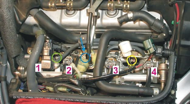
To get the engine’s intake tracks in sync the four throttle body plates need to be adjusted to match each other’s air flow. The throttle bodies are linked in pairs. TB’s #1 & #2 have an adjustment screw that adjusts their linkages. TBs #3 & #4 have a different adjustment screw that adjusts their linkages. The two pairs are linked together by a third adjustment screw.

This is a simple procedure but does take patience. The image above shows TBs #1 & #2 on the left and the linkage adjustment screw for this pair is circled in green. TBs #3 & #4 are on the right and their adjustment screw is circled in yellow. The blue circle is the approximate location of the linkage screw that adjusts the two pairs together. This screw is only accessible when the throttles are twisted about ¾ of the way open—so the engine has to be off to gain access to this screw. Here’s how to make the adjustments:

1. Get the engine hot by going for a short ride. When you are at 4200 RPM (Gen I, the rpm number will be slightly lower for Gen IIs) in 3rd or 4th gear, squeeze you heals against the frame to feel the level of engine vibration. This highly precise measurement will be used later to determine how good a sync job you did.

2. Raise Tank and connect sync tool.

3. Turn all four air adjusting screws on each throttle body (not the throttle linkage screws) in until they are lightly seated.

4. Back each screw out 1 turn

5. You may want to place a large fan in front of the radiator to keep things cool (including you).

6. Start the engine.

7. The TBs will probably be out of sync at idle. The actual vacuum levels that your sync tool shows does not matter—we’ll fix idle sync later in the procedure.

8. REVING THE ENGINE Slowly rev the engine up to around 4000 RPM while watching your sync tool. What you are looking for is even vacuum levels as engine speed increases. If you try to perform to sync the TBs with the engine speed steady (say at 4000 RPM) you will find that the vacuum levels between each TB will never be in sync no matter how many adjustments you make. It is more important for vacuum levels to be even during moderate, smooth, engine acceleration and not at a steady throttle setting. You will have to rev the engine multiple times to get a feel of where the vacuum levels are at for each throttle body.

9. Using the butterfly sync screw between TBs #3 and #4 (Yellow Circle) adjust the vacuum level so #3 and #4 are the same when you accelerate the engine as described in Step 8, “REVING THE ENGINE above. This will take several tries. You may not get them exactly even either, but get them as close as you can (usually within 1 cm of Hg.).

10. Now perform the same procedure on TBs #1 and #2 (Green Circle). You may have to rev the engine half a dozen times to get them close.

11. With vacuum levels for TB pairs #1/#2 and #3/#4 matched it’s time to sync the two pairs of TBs together.

12. Rev the engine as described in step 8, REVING THE ENGINE while watching the two pairs of TBs. If they are off by more than 1 cm or Hg., an adjustment is needed.

13. The adjustment screw can only be accessed with the engine off. The screw is located between the two pairs of TBs (Blue Circle with Arrow). (The throttle has to be opened about ¾ of a turn to get a screw driver on the screw). Turn the screw about 1/8 of a turn (either direction) and restart the engine.

14. Check the balance (vacuum level) between the two pairs of TBs. Shut the engine off and readjust as many times as needed. If turning the third screw 1/8 of a turn in one direction, turn the screw the other direction and check vac levels again. (By now you and your FJR’s cooling system will appreciate the large fan you are using, step 5.)

15. When the two pairs of TBs are even (when you smoothly rev the engine) you are finished with this step. To be too anal about how close the vacuum levels are. Get them as close as you can.

16. Now let the engine idle. Adjust the idle speed to 1000. The tach on the FJR is very accurate. I checked it against a $500 electronic sync tool that counts the vacuum pulses during the intake stroke of cyl #1 and then generates an RPM signal on the tool.

17. Now it’s time (finally) to adjust the airscrews on each TB. Use cyl #3 as reference and adjust the other cylinders to the same vacuum level as #3. The actual level does not matter (I know, everyone seems to be hung up on how may cm of HG., but it really doesn’t matter as long as idle speed is kept at 1000 RPM.)

18. Make a final idle adjustment (1000 RPM) and you done. If after syncing the TBs with the airscrews you can’t get the idle speed to come down to 1000 rpm, DON’T KEEP BACKING THE IDLE ADJUSTING SCREW OUT because is will unthread from the throttle linkage. If idle speed won’t come down to 1000 rpm the TB airscrews all need to be turned in ¼ to ½ turn (make sure you turn them in all the same amount). Now the idle adjusting screw will allow you to adjust the idle speed to down to 1000 rpm.

19. Last step. Go for a ride and check engine vibration at 4200 RPM (Step 1), it should be better than when you started. If it’s worse, you screwed up the adjustment. The amount of improvement really depends on how far out of the sync the TB linkage was before you started. When done correctly most of the vibration you normally feel at 4100/4200 RPM in fourth/fifth gear should be gone—at least it was on my 2005. Good Luck!

If you're interested in electrical stuff on your FJR, check out my book "Motorcycle Electrical SystemsTroubleshooting and Repair" on the vendor's page. Tracy...

 
Last edited by a moderator:
Here is the "ridiculous procedure"
I said "ridiculously complex" :p

Well, what I read before didn't make much sense; this is CRYSTAL CLEAR. Thanks a bunch for posting this man. I think I can speak for the entire board thanking you for taking the time to write this.

Let me just make one correction: On step 18, you DO want to set TB #3 to 250mmHg for 2 reasons. First, it allows you to be able to adjust the idle speed properly; doesn't take a minute to set #3 to 250mmHg first. And second, the ECU is reportedly sensitive to vacuum levels, especially at closed throttle, so you want those suckers as close to spec as possible.

Man, this is A LOT more complicated than all other bikes I've had, but thanks to you, we now know how our TBs are interconnected to each other. Now this procedure is officially changed from 'unauthorized' to the [SIZE=14pt]'3 dogs synch procedure'[/SIZE] :clapping: . Again, thanks buddy. Take care gang.

JC

PS. Mods, it'd be nice to pin this. Or just add it to the 'Bin of Facts' of both GenI and GenII.

 
Last edited by a moderator:
Hi JC, many have posted on this so no need to repeat it all...I set the 250mm on #3, ran the idle TBS to within 10MM, ran it slowly up to 3500 (my normal cruise) and noted some lead/lag but was able to get the t bodies synched with 10mm or less easily at a steady cruise rpm...however, that required I reset #3 (as #3/4 screw required adjustment - 4 was high at 3500) to 250mm slightly at idle with the airscrew again...I then ran out of adjustment on #1 at idle (air screw all the way in and still low compared to #3...so I reduced #3 to about 240-245 and then was able to get'em all >10mm at idle (may be guage error with 250mm on my Morgan being higher than indicated)...the last adjustment at 1100 miles last week was my third, and it hadn't changed much from the first at 300 mi and second at 600 (essentially the same info as in PM sent earlier)...now to experiment with BM with uniform values for all four.

Gary in Fairbanks

 
Last edited by a moderator:
I understand the theory but I'm not totally sure that this is necessary. Ever since the CV carb and later FI bikes, the butterflies become almost non-existent in the Fuel/Air equation at rpm's above a certain point which isn't all that high. If you get a better performance, real or perceived using this method, go for it. IMO, if you just look at the butterflies and see they are breaking open at exactly the same time, you are OK. That may be why you don't see it in the service manual. This is pure speculation, but I would guess the air screws are used to get the four TB's at a common start point for the ECU and its sensors to allow it a more efficient map utilization. IMO, you run the risk of getting the ECU to chase its tale like the case of using a PCIII with an O2 sensor connected.

 
Sprint, nobody can claim power gains with a proper TB (unless way off); it's all about SMOOOOOTHNESS. Haven't done it on the FJR yet (waiting for tool), but just to give you an example, on my SV1000, the difference in smoothness with only 1/16 of a turn (on throttle plate screw) was incredible. Didn't notice an improvement (how engine sounded or felt) at idle, even though it's a V-twin, but before, my hand started tingling almost immediately, and after, not a problem even on a 300-mile ride. Remember cruising requires very little throttle opening. You're correct in pointing out at much larger openings the difference becomes less and less.

As a comment, even before I adjusted the synch in the SV, it was within spec. Just to show the difference a precise synch does to smoothness. Oh, and the slight surging was gone too. Hope to be able to do a similar job on the FJR, with the hopes of knocking down the surging a few notches.

JC

 
Last edited by a moderator:
I understand the theory but I'm not totally sure that this is necessary. Ever since the CV carb and later FI bikes, the butterflies become almost non-existent in the Fuel/Air equation at rpm's above a certain point which isn't all that high. If you get a better performance, real or perceived using this method, go for it. IMO, if you just look at the butterflies and see they are breaking open at exactly the same time, you are OK. That may be why you don't see it in the service manual. This is pure speculation, but I would guess the air screws are used to get the four TB's at a common start point for the ECU and its sensors to allow it a more efficient map utilization. IMO, you run the risk of getting the ECU to chase its tale like the case of using a PCIII with an O2 sensor connected.
Hello, JC's likely correct about the smoothness versus necessity...vacuum taps from all four throttle bodies exit next to the capped ones we use to do an idle/cruise sync, and are connected and fed to the single input on the intake manifold pressure sensor on the top left of the fuel rail...from what I read the ECU uses an averaged vacuum value from that sensor converted to voltage to determine intake pressure, that's then converted to air flow volume (load) by the ECU with the help of the TPS...when used in conjunction with data from engine speed, crank position, intake air temp, and exhaust O2 info, the ECU sets injector output/timing and ignition timing...so making an adjustment to just one TB would likely have a diluted effect to the intake sensor output...but may help with the vibration and harmonics we feel as ops...keeping all outputs around 250mm at idle as recommended probably is important as the Shop book asks for it to be there for some obscure reason, probably to give the ECU a proper starting point as you noted.

Gary in Fairbanks

 
Last edited by a moderator:
Sprint, nobody can claim power gains with a proper TB (unless way off); it's all about SMOOOOOTHNESS. Haven't done it on the FJR yet (waiting for tool), but just to give you an example, on my SV1000, the difference in smoothness with only 1/16 of a turn (on throttle plate screw) was incredible. Didn't notice an improvement (how engine sounded or felt) at idle, even though it's a V-twin, but before, my hand started tingling almost immediately, and after, not a problem even on a 300-mile ride. Remember cruising requires very little throttle opening. You're correct in pointing out at much larger openings the difference becomes less and less.
As a comment, even before I adjusted the synch in the SV, it was within spec. Just to show the difference a precise synch does to smoothness. Oh, and the slight surging was gone too. Hope to be able to do a similar job on the FJR, with the hopes of knocking down the surging a few notches.

JC
I'm not talking power gains either. When I did the first TBS it made significant differences with that throttle snatch business and I had a PCIII installed too. It also gave me a 2mpg mileage increase. My only issue is that IMO if the butterflies are breaking properly, don't mess with them.

 
Performing the unauthorized TB sync does not add any power. However the amount that each butterfly is open is significant in that the fuel injector for that throttle body will inject an exact amount of fuel based on all the sensor inputs to the ECU. When the fuel map was programmed the same amount of air flow (within a tolerance/range) through each throttle body was assumed by the programmer. If the sync between cylinders is off by more that whatever that tolerance is, some cylinders may run rich or lean depending on more or less air flow.

The TB sync that I wrote will however cause most of the 4000/4200 rpm (gen I) vibrations to be eliminated. I have had a dozen FJR riders who attended the Total Control class that I teach ride my bike and they all commented that mine had less vibration than theirs at that engine speed.

 
TB synch will add power, if one tb is not opening completely at full throttle. I guess a more accurate claim would be that it restores power that was lost with the incomplete opening. It will not increase power over and above that already available.

 
However the amount that each butterfly is open is significant in that the fuel injector for that throttle body will inject an exact amount of fuel based on all the sensor inputs to the ECU. When the fuel map was programmed the same amount of air flow (within a tolerance/range) through each throttle body was assumed by the programmer.
A related question, which I haven't tried yet:

Since fuel and air is supposed to be the same for each piston, why the CO values from the factory are not uniform?? Since we don't know the % change from each injector, wouldn't make sense to just put all the values at +18 (currently 5,18,18,21), like it was reportedly done to a bike in Italy, I think, recommended by a Yamaha tech? Just curious.

And yes, I also agree that if TBs are not synched properly, engine would make more power afterwards. Guess the more accurate way to describe it would be that power gains are insignificant, unless synch is really messed up.

Thanks guys for all your help.

JC

 
Last edited by a moderator:
A related question, which I haven't tried yet: Since fuel and air is supposed to be the same for each piston, why the CO values from the factory are not uniform?? Since we don't know the % change from each injector, wouldn't make sense to just put all the values at +18 (currently 5,18,18,21), like it was reportedly done to a bike in Italy, I think, recommended by a Yamaha tech? Just curious.
Sorry to dredge up such an ancient topic, but ELP_JC raised a question here that was never answered or addressed, and deserves a second look IMO.

My guess is that the CO settings are different due to intake manifold design or some such. So even with perfectly syncronized butterflies the CO still needs to be different. The only twist is that the newest 2nd gens, which have basically the same engine and intake, come programmed with even CO numbers (10, 10, 10, 10, as I recall).

Either way, both the air screw and the CO settings should have the biggest effect at idle, with diminishing effect as the throttle is opened further. Most likely this was a way for Yamaha to meet their emissions specs at idle and has little effect on engine smoothness at off idle.

So maybe setting them all the same will make the bike slightly smoother at the cost of greater emissions? :unsure:

Thoughts?

 
Last edited by a moderator:
My guess is that the CO settings are different due to intake manifold design or some such. So even with perfectly syncronized butterflies the CO still needs to be different. The only twist is that the newest 2nd gens, which have basically the same engine and intake, come programmed with even CO numbers (10, 10, 10, 10, as I recall).
Thoughts?
I still believe that the CO2 settings come pre-programmed in the ECU. A different batch of ECUs may have different settings from another batch but all within the batch are the same.

I would think that a QC check of several bikes per run for the required emmisions level for sale in the USA is all that Yamaha needs.

Production quality is at a level that the engines and components are pretty much the same and as such, there is no need to adjust levels on different bikes (at the factory). The fact that the levels on my replacement ECU were the same as stock is what strengthens my thoughts.

 
Maybe its by design. I've rejetted old I-4 engines that had different jets on the outside cylinders. Recommended new jeting followed the same pattern. The explanation was that the inside cylinders ran hotter and required different jetting.

 
Maybe its by design. I've rejetted old I-4 engines that had different jets on the outside cylinders. Recommended new jeting followed the same pattern. The explanation was that the inside cylinders ran hotter and required different jetting.
True, I did a bunch of mods to a Vtwin a few years back and the rear cylinder required +4 jet sizes to compensate for the different operating temps. Man, the first few times I had the carbs out took about 45 minutes each time. After rejetting it about 25 times (whole range, not just mains) I had that down to about 20 minutes.

 
Great, today is the day I go out to do this, and the photo is now gone from this post. I'm sure I can figure it out, but from now on I guess I'll save any photo's I think I might need later. :rolleyes:

ON EDIT: wow. must be a photbucket issue, now I can see it again. I'll snag it so it doesn't vanish again for me.

 
Last edited by a moderator:
Top