Mihalis fjr
Well-known member
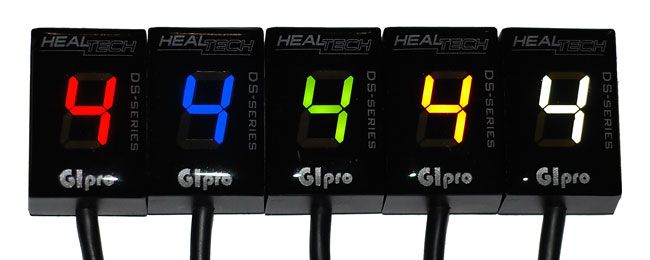
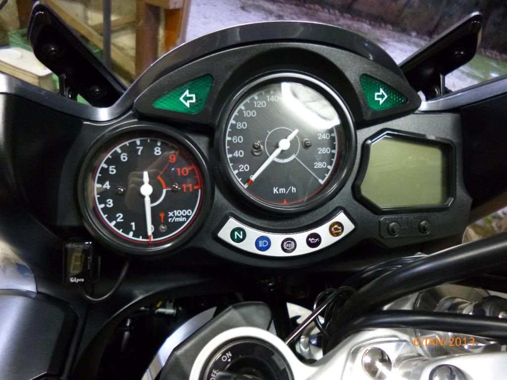
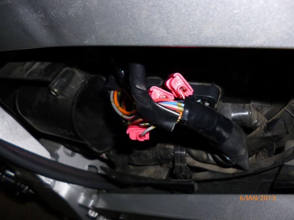
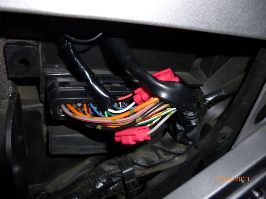
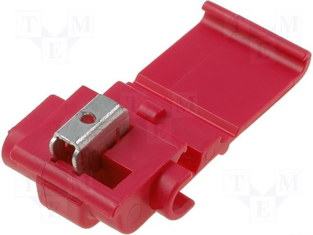
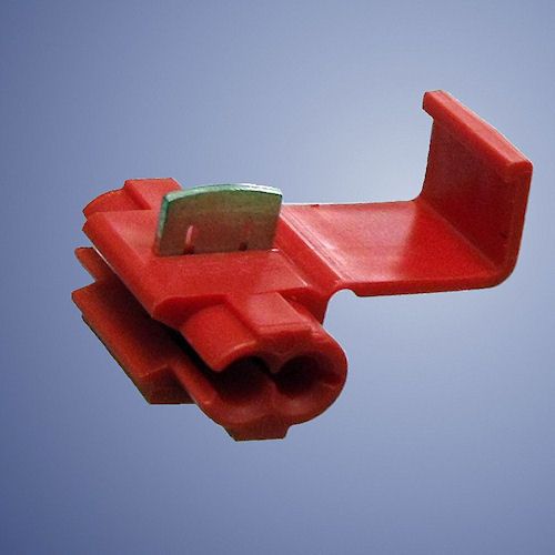
Just today i installed this elegant and useful gear indicator.The installation was very easy!The kit had 4 wires that i splice these with the included scotchlok without to need cutting or soldering any wire,near to the ECU coupler.
The black wire i screwed it in the screw that hold the toolbox in the frame over of the ECU.
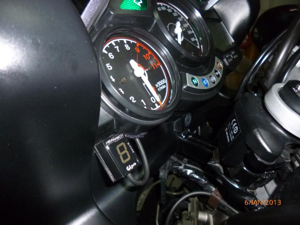
The small wire harness i passed it under the tank and took it out from the opening that the clutch hose goes to the frame opening.
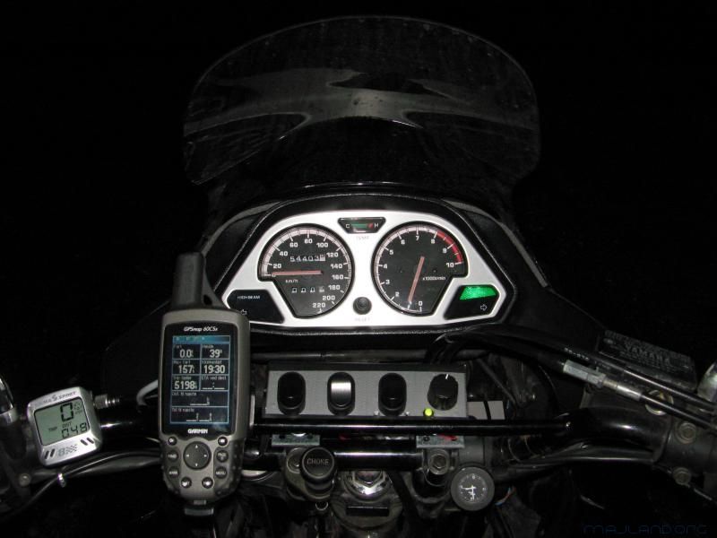
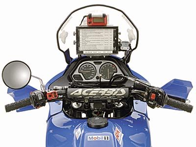
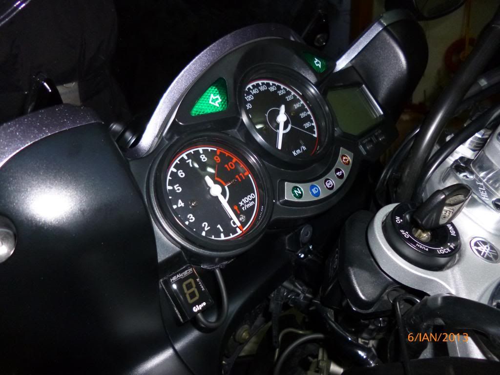
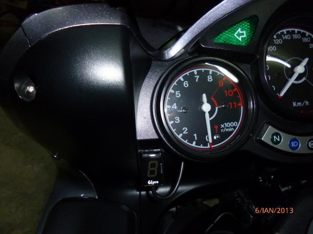
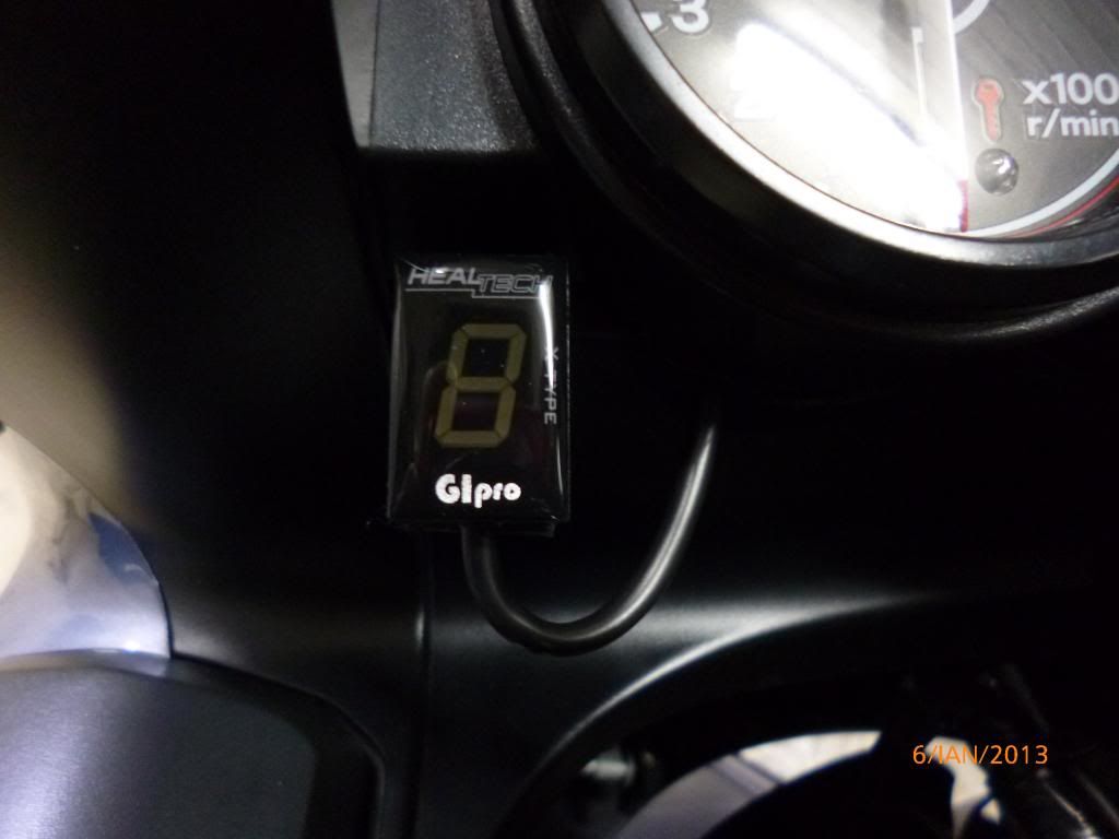
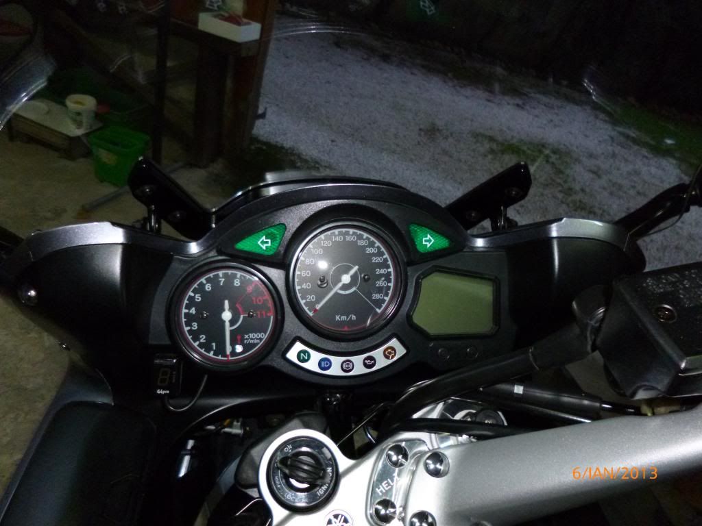
Τhe small digital screen i put it on a small plastic home made mount a bit longer than the screen and i glued, the plastic mount down of the meters with a automotive double adhesive tape and the digital screen on the mount with velcro tape for easy removing when i need to remove the dash panel.
The following instructions came from a friendly person from the Gipro healtech electronics..:
> 2) Splice the Red GPX wire to any +12V switched power lead, e.g. to the> Red/White wire at the ECU connector.> > 3) Splice the Black GPX wire to chassis ground, or the negative battery> terminal.> > 4) Splice the White GPX wire to the White/Yellow (speed signal) wire atthe> ECU connector.> > 5) Splice the Green GPX wire to the Gray (crankshaft sensor signal) wireat> the ECU connector.> > > Note: For splicing, wire tap connectors are included. No need to cut or> solder any wires.
https://www.healtech-electronics.com/
I post and some photos..

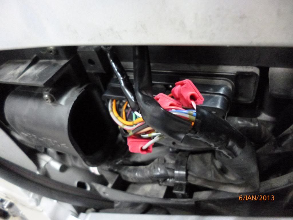
The black wire i screwed it in the screw that hold the toolbox in the frame over of the ECU.
The small wire harness i passed it under the tank and took it out from the opening that the clutch hose goes to the frame opening.
Τhe small digital screen i put it on a small plastic home made mount a bit longer than the screen and i glued, the plastic mount down of the meters with a automotive double adhesive tape and the digital screen on the mount with velcro tape for easy removing when i need to remove the dash panel.
The following instructions came from a friendly person from the Gipro healtech electronics..:
> 2) Splice the Red GPX wire to any +12V switched power lead, e.g. to the> Red/White wire at the ECU connector.> > 3) Splice the Black GPX wire to chassis ground, or the negative battery> terminal.> > 4) Splice the White GPX wire to the White/Yellow (speed signal) wire atthe> ECU connector.> > 5) Splice the Green GPX wire to the Gray (crankshaft sensor signal) wireat> the ECU connector.> > > Note: For splicing, wire tap connectors are included. No need to cut or> solder any wires.
https://www.healtech-electronics.com/
I post and some photos..
Last edited by a moderator:


")