ionbeam
2 FUN
[Pre-Edit -- FU Photobucket, to view the photos you will need to install one of these addons Firefox fix Chrome fix ]
Starting in '13 the FJR got a Fly By Wire throttle body system. As part of the TB updates, a new design Throttle Position Sensor was added and moved to the left end of the throttle body rack. By 2016 it is looking like there are some of the new design TPS which are going bad. red2kcbr diagnosed his driveablilty problem as a bad TPS and changed it with a new part. This fixed his driveablity problem so it strongly indicates the TPS was defective, red2' sent me the TPS so I can take a look at it.
The physical construction of the TPS is different than the previous type used on all cable controlled throttle body racks but the electrical design remains the same.
The bad TPS that red2' sent me was P/N 2S3-85885-00.It had a date code stamped on the side -- Date Code 4314E which is the 43rd week of 2014; the E may be a plant or batch code. Edit on 9/7/16 -- Fred W's TPS seems to prove that this is not a date code, meaning now unknown. The FSM says the TPS should be 1.20-2.80 k Ω and the sensor output should be 0.63-0.73 V at idle. The old TPS had only one output, this TPS has two outputs. This is the schematic view of the TPS:
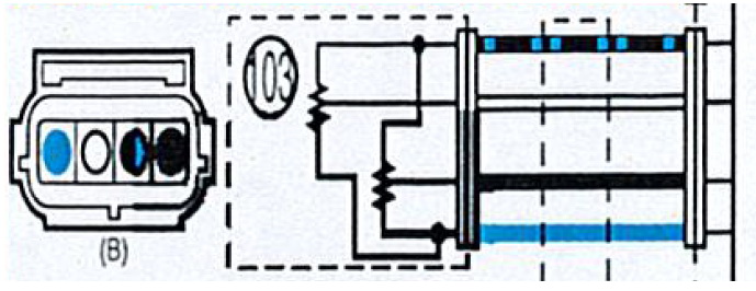
The colors of the pins in the connector correspond to the wires. The sensor (item 103) has two resistors in parallel with two wiper outputs. The blue wire is a +5 reference voltage from the ECU and the Black/Blue wire is reference voltage ground. The right side of the diagram is the ECU, the wires make no other stops between the sensor and the ECU. The resistors in the bad TPS measured 1.86 k Ω The wiper value went from 0.380 Ω to 1.86K Ω which is correct for the part.
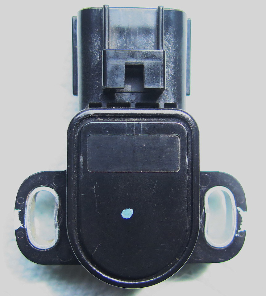
Top view of the TPS with a blue dot. Dunno what if anything the dot signifies. The metal sleeved holes allow the TPS to be slightly rotated to calibrate it for idle voltage.
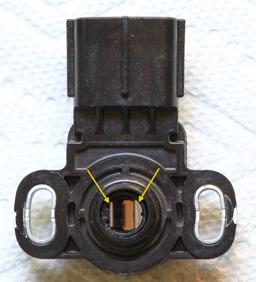
This side connects to the long center rod that the throttle plates are connected to and it is different than the previous TPS connection. The center pivot rotates 90°. As the throttle plate rod turns it rotates the wipers inside the TPS in lock-step with the plates. The lobes of the center pivot are not symmetrical so it can key onto the throttle plate rod in only one way.
Here is a family picture when the sensor is taken apart.
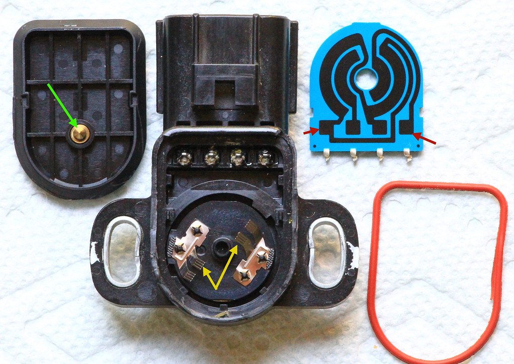
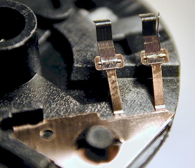
The item in the upper left is the cover for the sensor, the green arrow points to the self centering pivot that keeps the wipers turning in circular alignment. The orange ring on the right is a weather seal that goes between the cover and the body of the sensor. In the center of the picture is the main body of the sensor. The yellow arrows point to the wipers which ride along the resistor patterns and pickup a varying voltage off of the circuit. The back side of the plate with the wipers is the keyway which goes on the throttle plate rod. In the upper right is the resistor board, it is upside down, it normally faces down over the wipers. I had to clip the leads which leave the board and go to the connector pins. The blue board is in two layers, the pins connect to the resistor material with an internal connection at the squares which the red arrows point out.
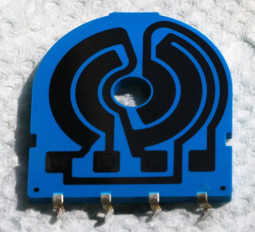
As the throttle plate rod rotates the wipers are dragged along the resistor trail. When the wiper is at one end of the trail it sends ~.0680 volts to the ECU. The ECU converts the voltage to a digital value, does some math and recognizes this as the throttle plates being 17% open. This is the 17 you can read in DIAG when testing the TPS. As the throttle is opened up the wiper voltage goes up to ~4.5 volts, the ECU does some math and recognizes this as the throttle plates being 100% open. The voltage should linearly go up and down as the wipers slide over the resistors.
Pictures showing what is wrong with the resistors was problematic to get. The resistors are failing the exact same way as the TPS that I had in my '04 even though they are different physical materials. Picture attempt #1 to show the worn resistor material issue in a way that retains relationship to the part:
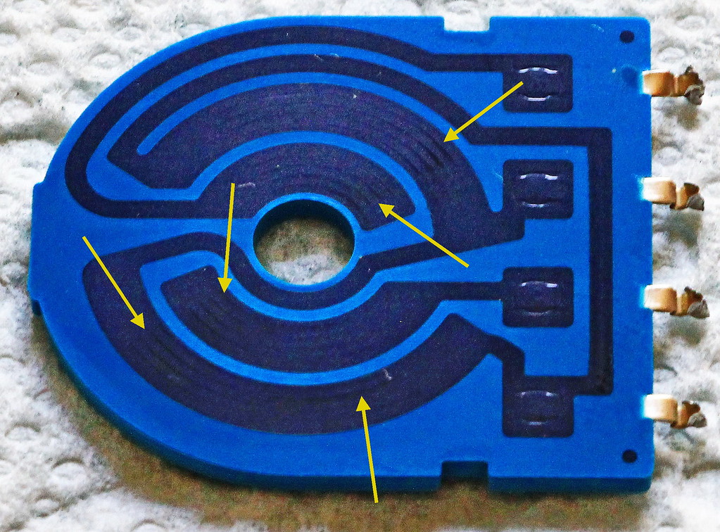
The arrows point to spots along the resistor where the wipers have cut into the resistive material. Once the resistor material gets thin and/or cut it becomes very susceptible to heat causing the resistor value to drift causing erroneous voltages or the wiper simply makes no contact and the voltage drops below 0.680 V which the ECU sees as closed throttle plates. The voltage climbs as the throttle is opening, the ECU sees the throttle opening 20%, 25%, 30% then suddenly going to 0% then as the wiper gets back on good resistor material it suddenly jumps from 0% to 35%. You feel like the throttle was cut and then snapped open creating a really rough ride.
Picture #2 below is taken at an angle so the glare can show just how cut up the resistor material has become:
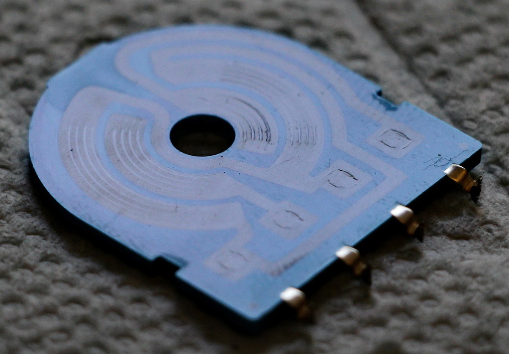
The deepest wear happens where the throttle is most commonly used. Typically it is at idle and then roughly at 30%-40% of throttle opening where you cruise. The failure of the TPS is a slow wear-out and not a sudden break down. Edit to add: The right side pair of wipers go from the bottom of the sensor (idle) up to the top (WOT). The left side goes from the top (idle) to the bottom (WOT). Both right and left resistor tracks had heavy wear from idle to ~40% throttle.
Beginning TPS failures may only show symptoms when hot, and this is hard to diagnose; as the TPS continues to degrade it will become easier to measure the failure. red2's TPS had failed, yet at room temperature measuring static resistance it tested good. The Gen III Yamaha Diagnostic Tool should allow a dealer to data log the TPS signal which should immediately and clearly show a failing TPS. Unfortunately, this kind of failure will normally pass DIAG and a passive resistance check.
If there really is a fundamental problem and Yamaha starts seeing lots of failures caused by the materials the TPS is made from there will probably be a Technical Service Bulletin (TSB) put out and a Rev. 2 TPS made available. If the issue is related to a date code, manufacturing plant or batch the TSB would instruct a dealer on how to inspect the part for the code (or dot color) and replace any TPS within the problem batch.
Starting in '13 the FJR got a Fly By Wire throttle body system. As part of the TB updates, a new design Throttle Position Sensor was added and moved to the left end of the throttle body rack. By 2016 it is looking like there are some of the new design TPS which are going bad. red2kcbr diagnosed his driveablilty problem as a bad TPS and changed it with a new part. This fixed his driveablity problem so it strongly indicates the TPS was defective, red2' sent me the TPS so I can take a look at it.
The physical construction of the TPS is different than the previous type used on all cable controlled throttle body racks but the electrical design remains the same.
The bad TPS that red2' sent me was P/N 2S3-85885-00.

The colors of the pins in the connector correspond to the wires. The sensor (item 103) has two resistors in parallel with two wiper outputs. The blue wire is a +5 reference voltage from the ECU and the Black/Blue wire is reference voltage ground. The right side of the diagram is the ECU, the wires make no other stops between the sensor and the ECU. The resistors in the bad TPS measured 1.86 k Ω The wiper value went from 0.380 Ω to 1.86K Ω which is correct for the part.
Top view of the TPS with a blue dot. Dunno what if anything the dot signifies. The metal sleeved holes allow the TPS to be slightly rotated to calibrate it for idle voltage.

This side connects to the long center rod that the throttle plates are connected to and it is different than the previous TPS connection. The center pivot rotates 90°. As the throttle plate rod turns it rotates the wipers inside the TPS in lock-step with the plates. The lobes of the center pivot are not symmetrical so it can key onto the throttle plate rod in only one way.

Here is a family picture when the sensor is taken apart.

The item in the upper left is the cover for the sensor, the green arrow points to the self centering pivot that keeps the wipers turning in circular alignment. The orange ring on the right is a weather seal that goes between the cover and the body of the sensor. In the center of the picture is the main body of the sensor. The yellow arrows point to the wipers which ride along the resistor patterns and pickup a varying voltage off of the circuit. The back side of the plate with the wipers is the keyway which goes on the throttle plate rod. In the upper right is the resistor board, it is upside down, it normally faces down over the wipers. I had to clip the leads which leave the board and go to the connector pins. The blue board is in two layers, the pins connect to the resistor material with an internal connection at the squares which the red arrows point out.

As the throttle plate rod rotates the wipers are dragged along the resistor trail. When the wiper is at one end of the trail it sends ~.0680 volts to the ECU. The ECU converts the voltage to a digital value, does some math and recognizes this as the throttle plates being 17% open. This is the 17 you can read in DIAG when testing the TPS. As the throttle is opened up the wiper voltage goes up to ~4.5 volts, the ECU does some math and recognizes this as the throttle plates being 100% open. The voltage should linearly go up and down as the wipers slide over the resistors.
Pictures showing what is wrong with the resistors was problematic to get. The resistors are failing the exact same way as the TPS that I had in my '04 even though they are different physical materials. Picture attempt #1 to show the worn resistor material issue in a way that retains relationship to the part:

The arrows point to spots along the resistor where the wipers have cut into the resistive material. Once the resistor material gets thin and/or cut it becomes very susceptible to heat causing the resistor value to drift causing erroneous voltages or the wiper simply makes no contact and the voltage drops below 0.680 V which the ECU sees as closed throttle plates. The voltage climbs as the throttle is opening, the ECU sees the throttle opening 20%, 25%, 30% then suddenly going to 0% then as the wiper gets back on good resistor material it suddenly jumps from 0% to 35%. You feel like the throttle was cut and then snapped open creating a really rough ride.
Picture #2 below is taken at an angle so the glare can show just how cut up the resistor material has become:

The deepest wear happens where the throttle is most commonly used. Typically it is at idle and then roughly at 30%-40% of throttle opening where you cruise. The failure of the TPS is a slow wear-out and not a sudden break down. Edit to add: The right side pair of wipers go from the bottom of the sensor (idle) up to the top (WOT). The left side goes from the top (idle) to the bottom (WOT). Both right and left resistor tracks had heavy wear from idle to ~40% throttle.
Beginning TPS failures may only show symptoms when hot, and this is hard to diagnose; as the TPS continues to degrade it will become easier to measure the failure. red2's TPS had failed, yet at room temperature measuring static resistance it tested good. The Gen III Yamaha Diagnostic Tool should allow a dealer to data log the TPS signal which should immediately and clearly show a failing TPS. Unfortunately, this kind of failure will normally pass DIAG and a passive resistance check.
If there really is a fundamental problem and Yamaha starts seeing lots of failures caused by the materials the TPS is made from there will probably be a Technical Service Bulletin (TSB) put out and a Rev. 2 TPS made available. If the issue is related to a date code, manufacturing plant or batch the TSB would instruct a dealer on how to inspect the part for the code (or dot color) and replace any TPS within the problem batch.
Last edited by a moderator:


