FJR Ignition Coil Voltage

Yamaha FJR Motorcycle Forum

Help Support Yamaha FJR Motorcycle Forum:

This site may earn a commission from merchant affiliate links, including eBay, Amazon, and others.

Constant Mesh

Well-known member
FJR Supporter
Joined
Jul 11, 2005
Messages
1,803
Reaction score
65
Location
Tenn
Each of the FJR's two ignition coils energizes two spark plugs simultaneously. Plugs 1 & 4 are wired in series with one coil's high voltage winding. Plugs 2 & 3 are wired in series with the other coil's winding. Since there are two air gaps to arc across in each coil circuit is a higher coil voltage needed for this circuit configuration?

Can a misbehaving plug affect the other plug's operation in their series circuit?

 
More amperage, but not voltage, IIRC. And yes, a bad plug can sap the system, but not to the point of outright failure of the good plug to fire. Weak, yes, dead, no.

 
Direct fire ignition systems like that have two separate coil windings inside each coil, one for each plug. Although the coil windings are separate for the individual plugs the windings are continuous...i.e....they are connected at the start of the windings. If you put an ohm meter on the two plug wires for that coil you should see continuity thru the high voltage windings for the separate plug leads.

One interesting facet of a direct fire system is that the voltage induced on the high voltage secondary coil windings is opposite in polarity on each of the plug wires. On one of the plug wires from any given coil the spark jumps from the center electrode to the ground electrode and on the other plug lead the spark jumps from the ground electrode to the center electrode.

Ignition systems set up like this are also called waste spark systems because they fire the plug every revolution of the crank instead of every other revolution when actually needed. The unneeded spark at TDC exhaust doesn't do anything but by firing both plugs at the same time every revolution of the crank the ignition system can function with only crankshaft position input. There is no need for cam position input or a half speed "distributor" for the system to work. This makes the ignition system much simpler.

I have never seen a fouled or shorted plug cause the other plug on that coil to mis-fire.

The system only generates as much voltage as is required to jump the gap anyway regardless of it's ultimate potential voltage (the ultra high number that race ignition salesmen love to quote). If 15Kv is all that is required to jump the gap then that is what you will see with a 'scope on the plug wire. The plug that is firing under compression loads will usually require more secondary voltage than the plug that is firing on the exhaust stroke with little pressure in the cylinder. So, each of the two secondary leads will show different voltages each time the coil fires depending on what that plug is doing on that stroke.

The primary voltage to the coil is unchanged at 12 v but the direct fire coils will draw more amperate as Rad says compared to a similar coil with only one secondary ignition lead.

 
Last edited by a moderator:
Jestal --

Are you saying there are three windings in each coil -- two high voltage secondary windings and one primary winding? Are all the windings totally isolated from the coil frame and ungrounded? Are the secondary windings electrically isolated from the primary winding -- no internal bus connection?

And, when you're measuring ohms between the two plug leads you're measuring two secondary windings in series with the two plug leads? Do you see an open circuit between one plug lead and the coil frame (ground)? Do you see an open circuit between the spark plug leads and the primary winding terminals?

Seems like if the two secondary windings have opposite polarity you'd end of with a net voltage of zero for the series circuit.

I assumed from the schematic that if you disconnected one spark plug wire that the other plug in the circuit wouldn't fire because there'd be no current return path to the coil.

 
Last edited by a moderator:
Jestal --
Are you saying there are three windings in each coil -- two high voltage secondary windings and one primary winding? Are all the windings totally isolated from the coil frame and ungrounded? Are the secondary windings electrically isolated from the primary winding -- no internal bus connection?

And, when you're measuring ohms between the two plug leads you're measuring two secondary windings in series with the two plug leads? Do you see an open circuit between one plug lead and the coil frame (ground)? Do you see an open circuit between the spark plug leads and the primary winding terminals?

Seems like if the two secondary windings have opposite polarity you'd end of with a net voltage of zero for the series circuit.

I assumed from the schematic that if you disconnected one spark plug wire that the other plug in the circuit wouldn't fire because there'd be no current return path to the coil.

Yes, three windings. One for the primary 12 volts and two for the high voltage...one for each plug lead. I The primary coil has a hot and ground lead I believe. It could go to ground internally if the 12 volt supply to it were switched by the ignition timing controller but in many cases the terminals for the primary are arranged so that there are two terminals. One is fed constant 12 volts and the "ground" side goes to the switching method so the ground is actually switched on and then off to generate the spark. An old automtive igntion coil was set up this way. 12 volts to the coil and the ground when to ground thru the points to activate the coil to create the spark. Remember points.....????

The secondary are also grounded internally in most cases that I know of. One side of the circuit actually operates as a positive ground though when it fires. Since the only voltage on that postive ground is for that coil it doesn't affect anything else...unless you somehow could ground that device back thru that internal coild winding I guess.

All this is based on background knowlege from automotive direct fire coil systems like this so I am pretty sure that the Yamaha system works the same but I have honestly never put an VOM on the coil leads to be sure. Something to try the next time it is apart......

 
Last edited by a moderator:
My take on the ignition circuit, based on the schematic of the ignition coils:

The FJR has two Ignition Coils, each Ignition Coil contain two windings -- a Primary winding and a Secondary Winding. The primary side winding has one side connected directly to +12 volts through the Run/Stop switch (red switch on right handlebar). The other side of the primary coil goes to the ECU which grounds the coil according to spark timing determined by the ECU. The secondary winding has two ends, each end goes to a sparkplug = two sparkplugs per Ignition Coil. Both plugs fire at once, one plug supplies ignition and the other is a 'waste spark' in the other cylinder.

When the primary side of the coil is grounded current flows and creates a strong magnetic field in the iron laminates in the coil. When the current is flowing it is essentially DC which can not be transferred to the secondary side, coils are AC devices. In a counter intuitive way, when the ECU releases the ground causing current to stop flowing in the primary side, the sudden drop in current is tantamount to AC. This causes the magnetic field created by primary side current to collapse. The collapsing magnetic field lines 'cut' across the windings of the secondary side inducing the high voltage output spike to the sparkplug. The coil is like a step-up transformer with few turns on the primary side and lots of turns on the secondary side. Example: if the primary side had 15 turns of wire and the secondary side had 15,000 turns of wire and you put 10 volts on the primary side then remove ground, the secondary side would produce a 10,000 volt output spike = 1:1,000 ratio. As Jestal mentioned about point ignition, it was when the points OPEN that a spark is generated.

The coil also has minimum and maximum charge rates. If you tried to run a car coil at motorcycle RPM rates the output voltage would start to fall off dramatically as RPMs climb. A motorcycle coil will have lower output voltages at lower RPM because it is optimized to run at higher charge/discharge rates created by high RPMs. Like HP and Torque you can't have it all, across all RPM ranges.

Also, as Jestal says, actual voltage at the sparkplug will vary based on many things. Without knowing the gauge of the wires in the coil I can't calculate actual output voltage and Yamaha doesn't say. I'm sure 15kV is very conservative for a .028 min gap plug, I would expect more on the order of 30kV POTENTIAL from the coils, with the actual voltage changeable due to afore mentioned variances.

 
Last edited by a moderator:
Here is an image from a book that I wrote for Motorbooks International. "How to Diagnose and Repair Motorcycle Electrical Systems" will be published this January, 2007.

6-3CoilDISFlowlores.jpg


As you can see the "DIS" (distributorless ignition system) coil has a primary and secondary winding. The basic difference between this coil and a conventional coil (used in a car with a distributor) is that the secondary windings are not connected to ground.

Power to the secondary circuit is induced via the primary winding. The secondary winding uses its power and ground to send the resulting spark through both spark plugs. One plug fires in the positive direction and the other in the negative. The cylinder head acts like a really BIG wire and connects the two plugs together.

The primary winding is controlled (switched on/off) by an electonic module or ECU that opens/closes the ground side of the primary coil winding.

Hope this helps.

 
3dogs diagram is exactly what the FJR has for coils and should match what I was trying to say. A picture is worth a thousand words... ;)

 
Last edited by a moderator:
So, for this scheme the same current flows through both plugs. The voltage drop across the arc may be different for each plug. But, the current is the same.

Also, if one plug wire is disconnected the circuit is open-circuited and thus neither plug will operate.

When the primary circuit is opened by the ECU, the AC voltage developed on the primary side will be V = L di/dt. Then, this AC voltage is transformed to a much higher voltage on the secondary side.

 
the primary side will be V = L di/dt. Then, this AC voltage is transformed to a much higher voltage on the secondary side.
Give the man some thick glasses in heavy black frames and a pocket protector. :nerdsmiley:
 
When I was in college one of my classmates broke his eyeglasses frame in the center between the lenses. He got a bit of scotch tape and rejoined the halves. The tape job lasted the rest of the semester.

He also had a strange habit for mending his shirts. He wore them until they were rags. When the threads gave way in a seam he'd break out the stapler and remake the seam.

One night a bunch of us visited him in his dorm room. He'd just been to the laundry downstairs and he had his wet clothes draped over makeshift clotheslines all around the room. He claimed he felt warmer with the increased humidity.

He was one of the most mild-mannered, meek friendly guys you'd ever meet. He never said a bad word about anybody. Yet, he could design and build a circuit like few others. Amazingly, his name was Fred.

 
3dogs, good diagram and exactly what I was trying to say.....I think.....LOL

CM, thanks for bringing this up. I always like it when someone causes some new thought on something old....

We have used that type of ignition system on several automotive applications for many years. Very reliable, incredible ignition energy potential, etc.

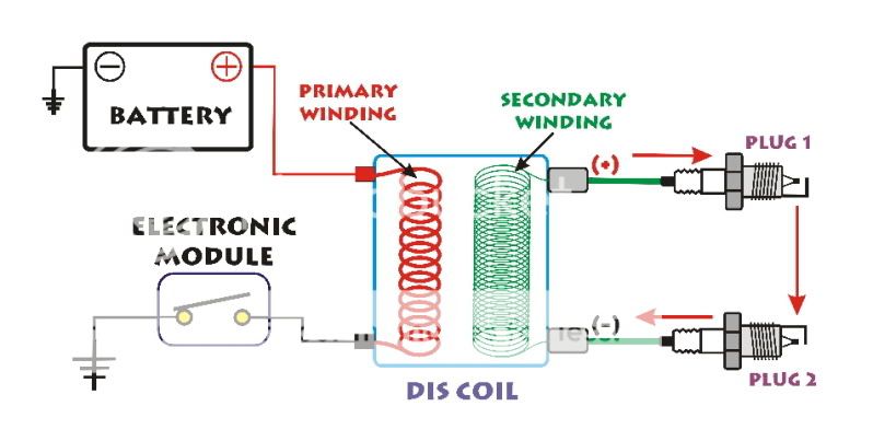
What threw me was the CM's question about opening one of the spark plug leads thus causing the other plug on that coil to go down as well. Along those lines, for some reason, I got into my head that the secondary windings had a ground connection in the middle of the coil. But, that didn't make any sense from past recollections and my gut level answer was exactly what 3dogs drew with the complete secondary coil feeding one plug lead + and the other plug lead - . If the secondary coil was not grounded in the middle and was an isolated coil winding only connected at the spark plugs to ground then how would one plug still work if the other were disconnected???

No one around here where I work seems to know why that other plug still will fire, though......LOL.

Indeed, our automotive (and I'm pretty sure all the motorcycle and other ignition coils like this) direct fire coils have an isolated secondary winding just like the diagram 3dogs drew.

From practical experience gained thru many diffferent trials (some deliberate and others not so....) I know that the "other" plug will still fire even if one plug is disconnected.

If one of the plugs fouls or the plug shorts to ground the answer is easy....that leg of the circuit is completed thru the ground or short and the other plug still works.

If one of the plug wires is off, that other plug still fires, though.

I have three possible explainations, based on discussions with co-workers, why....one is actually an observation and the others are theories that are yet to be proven.

First, as mentioned, those coils have tremendous ignition energy. The secondary voltage only goes as high as need be to jump the gap at the spark plug tip....or where-ever else there is a gap....like the plug wire off. My experience is that it is virtually impossible to "open" one leg of the circuit so as to disrupt the voltage path. The coil will simply generate enough voltage to jump whatever gap you create. Even pulling a plug wire off at the coil will cause the coil tower to arc to ground...almost 2 inches....and complete the circuit. Our coils like that can generate 50,000-60,000 volts in that situation I'm told(not continuous but temporarily before something melts.) That is plenty to jump most any practical gap that can be created on or around an engine. Even taking the plug wire off at the plug and dangling it into free space will cause the coil tower to arc past the boot and to ground at the coil so it just about impossible to really "open" one of the secondary circuit legs. This fits with my preconceived notions about those coils and fits from the experience I have had testing engines with those systems. So, practically speaking, I would say that the other plug still works because you cannot physically/realistically open the plug circuit on the other leg.

Secondly, some of the "experts" around here involved with the discussion so far think that if one of the legs of the secondary circuit is opened the voltage will go so high on the other plug that it will still start to ionize the gap of the plug thus initiating combustion even without a dedicated "spark" event. Possible, maybe, but not proven. I do know that the center electrode can get hot enough under some sitations (WOT, too hot of a spark plug) to initiate combustion without a "spark" and the giveaway is the ionization of the spark plug gap just before this pre-ignition event occurs. So, there is some basis for believing in the gap ionization with very high voltage idea. But not proven.

Third, some of the "experts" I work with are in the camp that think that the other plug will indeed NOT fire if the secondary voltage leg is interupted completely. They also think that they have never seen this happen (like me). The answer is is the first one given, that it is practically speaking impossible to open and isolate the secondary voltage circuit well enough to prevent an arc from occuring (given the basic OEM spark pllug cable/coil tower hardware on the machine). BUT, if you COULD isolate and interrupt the secondary spark plug lead on one leg then the other let wouldn't fire.

SOOO......more to follow as more experts I know weigh in. This is one of those questions that may have more than one correct answer. The practical answer is that the other plug keeps firing. Why is a bit of a mystery maybe. The theoretical but unobtainable answer is that the other plug will not fire....but that never happens. See the previous answer.

Personally, I think that the other plug will not fire if the secondary circuit could be interrupted completely and competely isolated from ground.....but I think you would play hell trying to accomplish this and you will get such a shock in the process.

Good thought starter. Never seen so many puzzled looks for a simple question. LOL.

 
Last edited by a moderator:
If one coil wire is disturbed, or otherwise unable to complete the circuit, the remaining one simply discharges to ground, and is lost in the clutter, or messing up your radio, the way a standard single coil would operate. The battery absorbs the volt spike, and since there is little in the way of actual current, no harm comes of it, other than circuit noise, one of the indicators that something is amiss in the ignition department of Feejer Power and Light. IMHO... :D

 
A coil internal schematic for a 'coil on plug' system is shown in the following:

https://www.asashop.org/autoinc/feb2003/mech.cfm

You can see an internal connection between the primary and secondary coil.

It would seem that the coil's secondary circuit is completed through the plug, the crankcase, the battery grounding lug & cable to the battery, and through the battery back to the + DC bus.

 
A coil internal schematic for a 'coil on plug' system is shown in the following:
https://www.asashop.org/autoinc/feb2003/mech.cfm

You can see an internal connection between the primary and secondary coil.

It would seem that the coil's secondary circuit is completed through the plug, the crankcase, the battery grounding lug & cable to the battery, and through the battery back to the + DC bus.

That's a different animal compared to the direct fire coil first mentioned....right? A coil-at-plug sytsem is just like a standard ignition coil in the sense that it fires only one plug much like an old coil/distributor system fired for each cylinder and the distributor routed the spark. Those all had to have the secondary voltage coil grounded internally to complete the circuit.

some of the "experts" involved
Does this mean that I've been voted off the island?

NO. Not at all. Not what I meant. Sorry for the confusion in my wording.

I was talking about the ignition system "experts" that I work with around here....er....at my work place.

Made more sense to me when I was typing it but realized the ambiguity in my wording so I edited it.

Still a couple of guys that know much more about ignition systems than me that I need to quiz on this idea.

 
Personally, I think that the other plug will not fire if the secondary circuit could be interrupted completely and competely isolated from ground.....but I think you would play hell trying to accomplish this and you will get such a shock in the process.

I talked to a couple of our ignition gurus today and they confirmed that this is true. Funny how they thought about it for awhile, too. None of use could remember actually achieving that situation due to the high ignition energy capability of the direct fire type coils. You would have to make some highly insulated hardware to actually open one of the high voltage circuits and keep it from arcing to ground.

 
Keep in mind the secondary voltage is soooo high, the coil will almost always find a ground. Many are the rotors I've seen with holes burned through, carbon tracks running down coil sides, and plug wires burned through when a bad wire or plug interrupted the normal voltage path.

 
Top