John_Dumke
Well-known member
Thanks to all that have helped me by posting clear and concise directions and photo's saving me time. This is my attempt return the favor.
Installation instructions for Hella FF50 lights with 3 position switch 1) Always On 2) Always Off 3) Come on with High Beams.
Parts to buy 1) Hella FF50, or other driving lights 2) Gaurald's brackets 3) Trick looking water proof switch and bezel (for two switches)
Step 1 - Install Blue Seas fuse box (optional), but keeps the Always On light position from draining the battery, if installed with relay to running light.
Step 2 - Remove plastic panels A, B, C, & D
Step 3 - Remove rear view mirrors
Step 4 - Figure out what to do with extra rubber pad Gaurald provides w/ kit. You can clearly see this rubber pad below the stock one. Garauld's bracket hugs the fairing closely, but doesn't touch it. There is a nice consistant gap. This piece of rubber provides extra support to the bracket since if fits in the gap snugly.
Step 5 - Trim rubber pad - With the rear view mirrow removed, place the pad on the back of the bracket and place the bracket w/pad where it will go, this provided me with an impression of dirt to trim the rubber pad to fit around the stock pad.
Step 6 - Glue rubber pad to the back of the bracket (I used rubber cement) and mount putting rear view mirrors back in place.
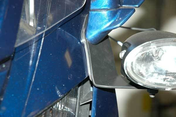
Step 7 - Drill mounting holes for lights
Step 8 - Locate FJR High beam relay and tap into. The photo below is the relay, it can be removed by moving it up and to the left off it's rubber mount. The red wire coming out of the back of this relay is how I tapped in.
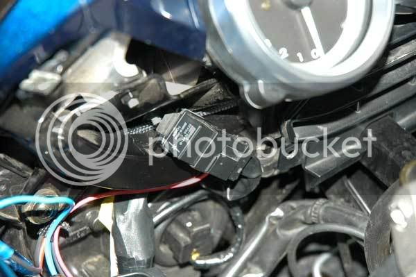
Step 9 - Remove the relay from it's base. Push the plastic protective sleave back as much as possible so that you can work with the wires. I use a small zip tie to hold the plastic sleave out of the way. Find the blue wire (it is not solid blue - it has a secondary color) and verify this is the correct wire with a volt meter. It should be 12v when the high beams are activated. Other people have used something called a positap? to tap into, I just remove a section of sheathing and solder in the new wire. This wire will go directly to the new DPDT switch.
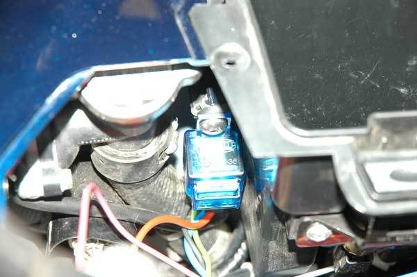
Step 10 - Mount the supplied Hella relay - I found a nice location for it adjacent to the radiator filler cap, bolting to the screw at the rear of the glove box.
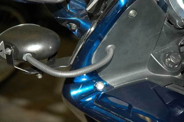
Step 11 - Run all of the wires across the nose of the bike. The wires will then be cut to length. There should be 4 wires, Red, Blue & Black (all coming from the Hella relay), and a second Black wire (coming from the left light, going to the right light and getting grounded). I ran these 4 wires above the horizontal square black metal support bar that is below the instrument cluster. A small wire helped feed the wires through this narrow area.
Step 12 - Drill the plastic panels and insert a grommet. I used a 3/8" grommet which require a 1/2" hole. I located the hole 3" down from the upper mounting hole and 1" in from the edge.
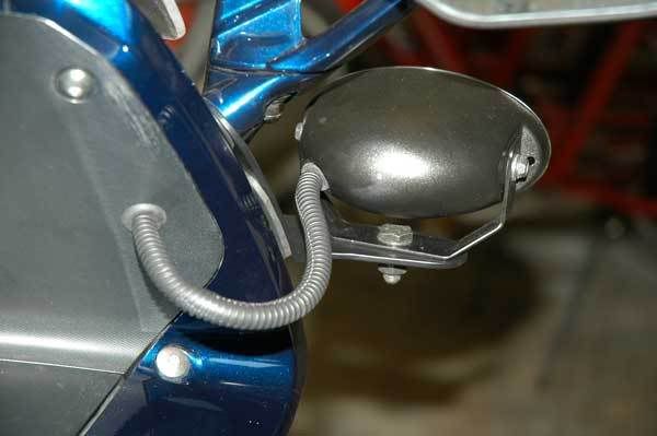
Step 13 - Figure out how to wire the DPDT switch, below are the pins on the back side of the switch and corresponding wires.
_____
| A B |
| C D |
| E F |
| G .. |
C - This is the lead to trigger the driving light relay.
A or E is then either 12v power (always on) or Relay power from High beams. I put the "always on" 12 volt power lead on E and FJR high beam relay on A.
D is ground
G is 12v power to power the indicator lights on the switch illuminating the switch when on.
Step 14 - Slightly expand the left accessory opening (used for heated grips) to put in bezel for two switches. You will need to expand the opening about a 1/16" in both direction. I trimmed the rear and right portion of the opening. I used a straight edge and a razer to do to this. The plastic is soft, and several passes will allow you make a clean edge.
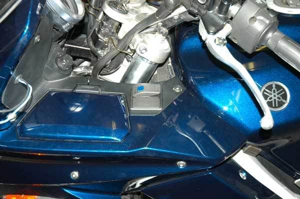
Where to Order DPDT switch - Get two end bezels, one DPDT switch, and a blank cover plate
Even though the plastic panel is slightly curved, the bezel fits in and conforms pretty well.
The detailed observer will notice that the switch cover is blue. This is a cover for a single throw switch. The red double throw switch cover has two plastic viewing windows, one large, and one small. This Red DPDT cover is MIA (2 hours looking for it, WTF) :headbonk: . I have the switch set where pressing the front edge is for the lights always on. This then gives the visual clue that it is on, and pressing the rear edge down will be for high beam actuation, where the red switch cover would have a smaller window, while the blue switch has no 2nd window.
Step 15 - Decide where you are going to get an extra ground and two extra 12v power supplies for the switch. I used the Red and Black wires at the base of the Hella Relay. Not really drawing any power, lights for the switch and actuation power for the Hella relay.
Step 16 - Trim all wires to length. Reinstall plastic panels.
Step 17 - Cut to lenth, and install plastic sheathing leading from light to gromett.
Step 18 - Adjust headlights.
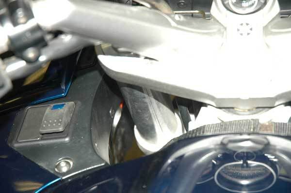
View From Cockpit - You can still nicely see switch.
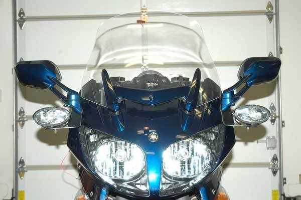
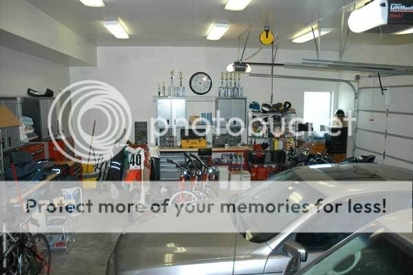
My kick *** garage! :specool:
Installation instructions for Hella FF50 lights with 3 position switch 1) Always On 2) Always Off 3) Come on with High Beams.
Parts to buy 1) Hella FF50, or other driving lights 2) Gaurald's brackets 3) Trick looking water proof switch and bezel (for two switches)
Step 1 - Install Blue Seas fuse box (optional), but keeps the Always On light position from draining the battery, if installed with relay to running light.
Step 2 - Remove plastic panels A, B, C, & D
Step 3 - Remove rear view mirrors
Step 4 - Figure out what to do with extra rubber pad Gaurald provides w/ kit. You can clearly see this rubber pad below the stock one. Garauld's bracket hugs the fairing closely, but doesn't touch it. There is a nice consistant gap. This piece of rubber provides extra support to the bracket since if fits in the gap snugly.
Step 5 - Trim rubber pad - With the rear view mirrow removed, place the pad on the back of the bracket and place the bracket w/pad where it will go, this provided me with an impression of dirt to trim the rubber pad to fit around the stock pad.
Step 6 - Glue rubber pad to the back of the bracket (I used rubber cement) and mount putting rear view mirrors back in place.

Step 7 - Drill mounting holes for lights
Step 8 - Locate FJR High beam relay and tap into. The photo below is the relay, it can be removed by moving it up and to the left off it's rubber mount. The red wire coming out of the back of this relay is how I tapped in.

Step 9 - Remove the relay from it's base. Push the plastic protective sleave back as much as possible so that you can work with the wires. I use a small zip tie to hold the plastic sleave out of the way. Find the blue wire (it is not solid blue - it has a secondary color) and verify this is the correct wire with a volt meter. It should be 12v when the high beams are activated. Other people have used something called a positap? to tap into, I just remove a section of sheathing and solder in the new wire. This wire will go directly to the new DPDT switch.
Step 10 - Mount the supplied Hella relay - I found a nice location for it adjacent to the radiator filler cap, bolting to the screw at the rear of the glove box.

Step 11 - Run all of the wires across the nose of the bike. The wires will then be cut to length. There should be 4 wires, Red, Blue & Black (all coming from the Hella relay), and a second Black wire (coming from the left light, going to the right light and getting grounded). I ran these 4 wires above the horizontal square black metal support bar that is below the instrument cluster. A small wire helped feed the wires through this narrow area.
Step 12 - Drill the plastic panels and insert a grommet. I used a 3/8" grommet which require a 1/2" hole. I located the hole 3" down from the upper mounting hole and 1" in from the edge.


Step 13 - Figure out how to wire the DPDT switch, below are the pins on the back side of the switch and corresponding wires.
_____
| A B |
| C D |
| E F |
| G .. |
C - This is the lead to trigger the driving light relay.
A or E is then either 12v power (always on) or Relay power from High beams. I put the "always on" 12 volt power lead on E and FJR high beam relay on A.
D is ground
G is 12v power to power the indicator lights on the switch illuminating the switch when on.
Step 14 - Slightly expand the left accessory opening (used for heated grips) to put in bezel for two switches. You will need to expand the opening about a 1/16" in both direction. I trimmed the rear and right portion of the opening. I used a straight edge and a razer to do to this. The plastic is soft, and several passes will allow you make a clean edge.

Where to Order DPDT switch - Get two end bezels, one DPDT switch, and a blank cover plate
Even though the plastic panel is slightly curved, the bezel fits in and conforms pretty well.
The detailed observer will notice that the switch cover is blue. This is a cover for a single throw switch. The red double throw switch cover has two plastic viewing windows, one large, and one small. This Red DPDT cover is MIA (2 hours looking for it, WTF) :headbonk: . I have the switch set where pressing the front edge is for the lights always on. This then gives the visual clue that it is on, and pressing the rear edge down will be for high beam actuation, where the red switch cover would have a smaller window, while the blue switch has no 2nd window.
Step 15 - Decide where you are going to get an extra ground and two extra 12v power supplies for the switch. I used the Red and Black wires at the base of the Hella Relay. Not really drawing any power, lights for the switch and actuation power for the Hella relay.
Step 16 - Trim all wires to length. Reinstall plastic panels.
Step 17 - Cut to lenth, and install plastic sheathing leading from light to gromett.
Step 18 - Adjust headlights.

View From Cockpit - You can still nicely see switch.

My kick *** garage! :specool:

Last edited by a moderator:


