Anatomy of a TPS

Yamaha FJR Motorcycle Forum

Help Support Yamaha FJR Motorcycle Forum:

This site may earn a commission from merchant affiliate links, including eBay, Amazon, and others.

ionbeam

2 FUN
Joined
Jun 24, 2005
Messages
8,817
Reaction score
1,785
Location
Sandown, NH
Judging from the number of failures of the Throttle Position Sensor I believe we can now rename it Total Piece of Shit.

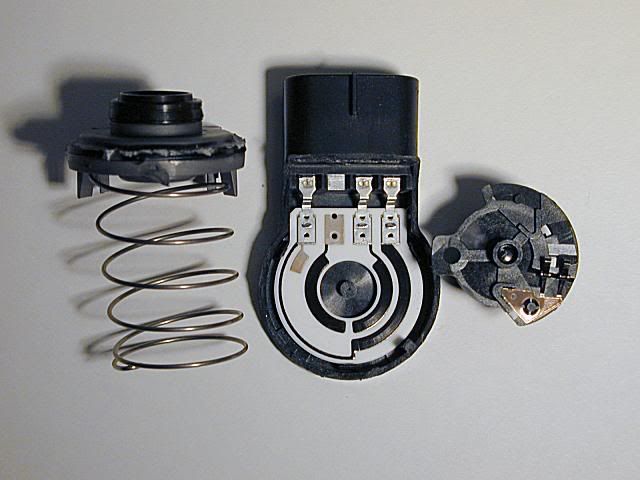
These are the three primary parts to the TPS.
Dscn0007sm.jpg


Attention to all you throttle spring releasers, the left side spring serves two functions. It is tightly wound to provide return spring tension for the throttle body shaft and ensures that the two pickup brushes (wipers) are firmly in contact with the resistors.

The center item is the actual body of the TPS. The black trails are resistive material screened onto the inert white backing. The far left terminal is Ground, the far right terminal is +5 volts from the ECU, the terminal just to the left of +5 is the signal terminal going back to the ECU. As the wipers slide along the resistor trails a varying voltage that is proportional to the throttle position gets returned to the ECU.

The right side object has the two pick up brushes, one riding on the +5 volt resistor and the other riding on the signal resistor. On my TPS the resistor that goes +5 volts to ground is 5.28k ohms and the resistor going to the signal terminal is <100 ohms.
Dscn0013sm.jpg


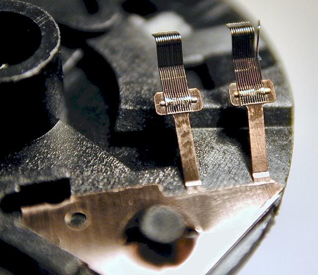
These are the two wipers that ride along the resistive material. They are made up of individual wires. Note the wiper on the right side, at the very right edge, has one wire bent out. The wipers themselves have strong spring tension which is then supplemented by the large holding spring.
Dacn0025smArrows.jpg


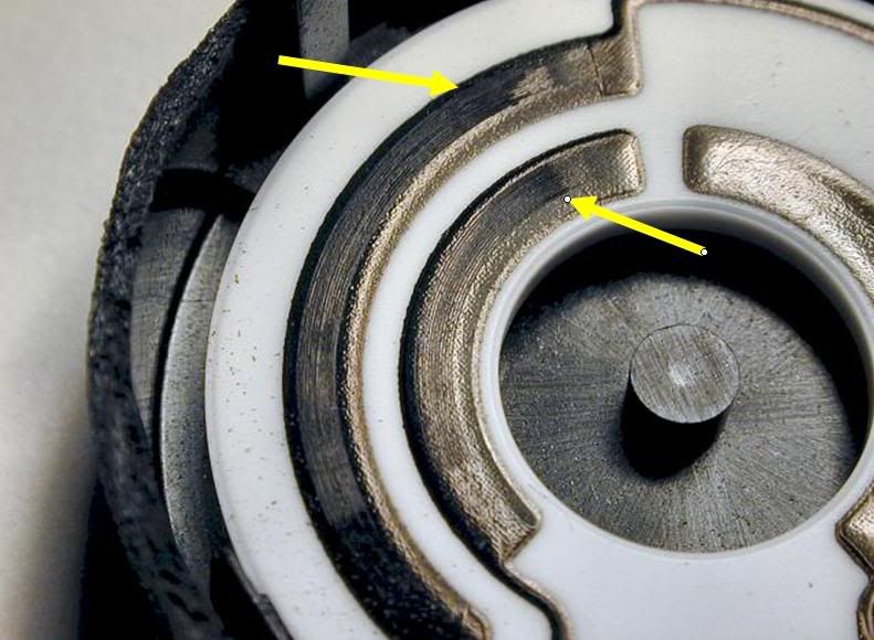
The arrows in the above picture show where the wipers sit at idle.
Dscn0027Selection2.jpg


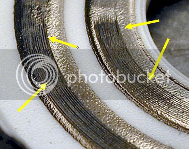
This is the source of the problem with the TPS. Normally, resistive material is carbon mixed with silica then fired to make a very hard glass like resistor. The TPS resistive material is made of a softer plastic type product. The wiper's individual wires actually have cut clear thorough the resistive material. When viewed under a microscope the base material is visible in the bottom of the grooves. Normally, this type of resistive material has its value determined based on it being a 'sheet', once cut the value will start to change. I measured a few of the furrows and they are just a bit wider than the wiper wires so there isn't sure contact side to side and the bottom is worn through. Additionally, and most importantly, the thinned material is no longer resistively stable under thermal changes. In particular, once it hits some critical temperature it goes from resistive to non-resistive. Said inversely, it goes from somewhat conductive to not conductive at all in those furrowed areas. This is one reason that a TPS can pass test at room temperature but fail once the engine heats up.

The arrows point out where the brushes have worn away the resistive material at idle and at roughly 25-30% throttle. For me that is around 3k RPM. You can also see that it has started to burn in the highly worn places.

The TPS I put in has a new P/N that is the same on the '06 so I take that to mean there has been some kind of a change to the part. It will take time or an autopsy of the '06 part to find out if it has been improved. I will note that my mostly solved surging is now back with the new TPS. I don't yet know if that is coincidence or related. My engine now runs with abrupt throttle response like the '06 people are reporting.

cool.gif


Last edited by a moderator:
Thank you for the great technical description of the TPS problem and the excellent pictures.

Too bad the replacement part for this creates new problems. :(

Hopefully I won't need to buy one until Yamaha gets the new problems solved. I assume they use these on many FI mdels so there is an incentive for them to get it right.

 
Outstanding write-up ionbeam!

Way to take the black magic out of it.

Question: Do you have any idea why more TPS's aren't failing? I have 88k on my FJR with no issues so far.

Now get to work on an 06 TPS!!!

 
I'd be willing to bet that if we compared manufacturing date codes we would know why some are failing and not others. The manufacturing process isn't always perfectly repeatable and a 'specification' has upper and lower limits. You aim for the middle but still pass even the squeakers. In this case I'm suspecting the resistive material or perhaps spring tension between the wipers and the resistors. Does somebody want to give me a good sensor to destroy :eek: while looking for variances?

 
Last edited by a moderator:
Good stuff, Alan, and great up-close photos. Thanks for taking the time. (BTW, what other site would someone bust their *** to help the society?? LERDOG you *******, are you reading this?)

This thing really is a piece of ****. They have been failing forever. Why they haven't gone with an optical encoder is beyond me. Tons more reliable and very accurate and repeatable.

-BD

 
Good stuff, Alan, and great up-close photos. Thanks for taking the time. (BTW, what other site would someone bust their *** to help the society?? LERDOG you *******, are you reading this?)
This thing really is a piece of ****. They have been failing forever. Why they haven't gone with an optical encoder is beyond me. Tons more reliable and very accurate and repeatable.

-BD

Brun puts the smack down on! :lol:

Nice write-up 'beam. You runnin' a PCIII?

 
Why they haven't gone with an optical encoder is beyond me.
Requires expensive damper couplings along with quadrature readings. Yamaha has so cheaply done the essentially open loop FI system I can't see them making the investment with out redesigning the whole system.

You runnin' a PCIII?
I'm not sure if it would have been a keeper without the PCIII. Maps 'n laptops rule!
 
Not to jump to the defense of Yamaha for a TPS that failed....but....TPS's in general have been a royal PITA to every manufacturer that uses one since they came into being back in the late 70's. There is always some new way for a TPS to fail. TPS's are always difficult because they see high use rates. Every time the throttle moves the least little bit the TPS comes into play. The TPS has much more activity at the idle and off idle and light throttle regions than in the higher throttle regions so the wear is very uneven over time. Also, engine vibration can cause the TPS to vibrate internally or "dither" at a specific spot which really increases the wear at that location. Then you have contaminant instrusion, moisture, etc. The guts of the Yamaha sensor look pretty familiar in comparison to some of the automotive TPS's I have seen over the years. Nothing earth shattering there or particularily failure prone. I suspect that Ionbeam hit the nail on the head with the comment about the production process of making the sensors. Somewhere along the line something probably slipped in the proces with certain date codes or production batches of sensors and those are the ones that fail. Possibly some lubricant that was supposed to be there isn't. Or maybe some moisture got into the sensor at the connector before the wiring harness was installed which reacted with the resistor element to cause the wear. Hard to say. But I have seen all those failure modes and many many more over the years of working with them. Then, of course, there is always a new supplier of the devices who can make it for less money (can you say "cheapest bidder"??) so that change in process and design is always factored in despite the best validation testing of the new design/supplier. It's nice to see that even the Japanese have quality control problems on occasion....LOL.

 
Dang, ya know even the TPS in my car failed at ~115k miles. Anatomy was much the same as the failed TPS from my FJR. Out of the 115k miles my car had at that time, roughly 500 miles of it was done 1/4 mile at a time at the drag strip. B)

 
... It's nice to see that even the Japanese have quality control problems on occasion....LOL.
With Mr. Jestal taking the stand, the star attorney begins the cross-examination: "So it is true then, Mr. Jestal, or whatever your real name is, that GM does have quality control problems??"

-BD

Requires expensive damper couplings along with quadrature readings. Yamaha has so cheaply done the essentially open loop FI system I can't see them making the investment with out redesigning the whole system.
Damper couplings? We're not talking that kind of resolution, besides, folded sheet couplings are cheap. Quadrature incremental encoders wouldn't do it, anyway - the bike wouldn't know where the throttle is at startup. But I bet some 6-bit absolute encoders can be made in China cheap!

-BD

** THIS POST EDITED BY AUTHOR FOR FAILURE TO AMUSE RATHER THAN INSULT **

 
Last edited by a moderator:
Everyone has quality control problems from time to time. Everyone. Toyota has even publicly admitted to delaying the introduction of several new models due to increasing quality control issues and declining customer satisfaction due to a myriad of problems.

... It's nice to see that even the Japanese have quality control problems on occasion....LOL.
So it is true then, Mr. Jestal, or whatever your real name is, that GM does have quality control problems??

Or "whatever my real name is...??" Not sure of where you are going with that comment but I use an internet handle just like you do. No attempt on my part to hide behind it, just common practice. You think I should post under my real name?? Get real.

Besides, how eactly, or thru what leap of logic, did you infer anything about GM or any quality problems they might or might not have from my comment...???

 
Last edited by a moderator:
Yea, gonna have to go with Jestal on this one.

What was up with that comment Brundoggy? Kind of an unwarranted slur/slam there if you ask me. Especially to somebody that's been so helpful on this forum. That ain't like you.

So wassup? Missus Brundoggy not letting the little dog play with his FJR again?

 
Brun does offer another way to measure rotational movement. He's not wrong, I'm not wrong, just different engineering solutions. My take on absolute encoders is that they are best when driven, with stepper motors being a good choice. My take on quadrature encoders is that they DO come with absolute position for reference but work best when following motion such as servo motors or rotary action such as following the throttle. In actual following applications I've found that quadrature encoders provide good resolution and it is easier to read the direction of rotation. I've never seen an encoder successfully used in a high vibration environment without some form of harmonic dampening in the shaft coupler. Brun's experience may be different.

After that cryptic bit, let me say that the resistor method of TPSing is by far the easiest and could/should be the best if, and it is a big [SIZE=18pt]IF[/SIZE] it can be done reliably. At >$70 it can't be considered cheap either.

Value of this post for the general population: <1%. ;) :rolleyes: :lol:

 
Everyone has quality control problems from time to time. Everyone. Toyota has even publicly admitted to delaying the introduction of several new models due to increasing quality control issues and declining customer satisfaction due to a myriad of problems.

... It's nice to see that even the Japanese have quality control problems on occasion....LOL.
So it is true then, Mr. Jestal, or whatever your real name is, that GM does have quality control problems??

Or "whatever my real name is...??" Not sure of where you are going with that comment but I use an internet handle just like you do. No attempt on my part to hide behind it, just common practice. You think I should post under my real name?? Get real.

Besides, how eactly, or thru what leap of logic, did you infer anything about GM or any quality problems they might or might not have from my comment...???
Jestal, I was joking. And apparantly, not well. The joke meant to sound like a lawyer asking you questions on the stand, now that you admitted fault. Or that's how it sounded in my head.

My bad. No offense meant to a significant contributor to this forum. Ignore me. Post edited in an attempt to set humor stage.

And no skooter, Missus Brundoggy is not letting the little dog play.

-BD

 
OK. No offense taken. Sorry I missed the humor side of it the first go 'round.

 
Attention to all you throttle spring releasers, the left side spring serves two functions. It is tightly wound to provide return spring tension for the throttle body shaft and ensures that the two pickup brushes (wipers) are firmly in contact with the resistors.
What a great write up; classic FJR forum info! Could you elaborate on the spring release mod impact on the TPS. Seems to me that the pickup brushes have enough problems without introducing a further cause for failure. What would be the symtoms of loose connecting brushes?

 
The big honkin' spring in the TPS is so strong that even if all the normal external throttle return springs were disconnected I think the TPS spring would still return the hand throttle to a fully closed position. It is another force to be overcome as you twist the throttle. Just a FYI for the springie guys. The TPS spring is not accessible without destroying the part so don't even think about it... ;)

The big TPS spring has a limit to the compression force it can exert on the brush assembly because of the center pivot. In the first picture, the resistor assembly has a post in the center, if you look close you may be able to see a small, slightly off center wear dimple. In the right hand side of the picture, the brush assembly is shown 'upside down', the center cup has a molded in half-round dome similar to a bearing. When assembled, the cup fits over the post of the resistor part then the spring gets keyed into the back of the brush assembly and gets wound up. The off center wear dimple on the center post was caused by the dome. The dome/post sets the mechanical compression limit. The little wear dimple being off center may be manufacturing variance or it could be the big spring is not loading the brush assembly perfectly flat.

What would be the symptoms of loose connecting brushes?
The brush(s) would loose contact with the resistor material causing the ECU to see 0% throttle opening. When I was cruising at ~30% throttle opening my TPS was sending ~.800 volts to the ECU. Once heat got to the TPS it would get flaky. As I passed from .750 to .850 volts it would go: .760 .780 .120 .120 .810 When the voltage dropped to .120 volts then went back up to .810 volts it was violent!!! First it would pitch me & pillion forward then slam us back. This was followed by hammering on my helmet to quit f'kn around. If the TPS voltage were to drop fully to 0 volts I'm sure the engine would stall. I believe Fabone knows what happens when you are leaned into a corner and this happens :glare: If the idle area of the resistor wears the ECU will see less than the minimum .620 volts and can cause a no start condition. It can also cause unexpected stalling as you are trying to pull away from a stop.
Hope you find an answer somewhere in all those words :blink: :lol:


Latest posts

Top