Challenging electrical questions

Yamaha FJR Motorcycle Forum

Help Support Yamaha FJR Motorcycle Forum:

This site may earn a commission from merchant affiliate links, including eBay, Amazon, and others.

Joe2Lmaker

Well-known member
Joined
Jul 1, 2006
Messages
2,162
Reaction score
50
Location
Fridley, MN
Here's what I'm up to:

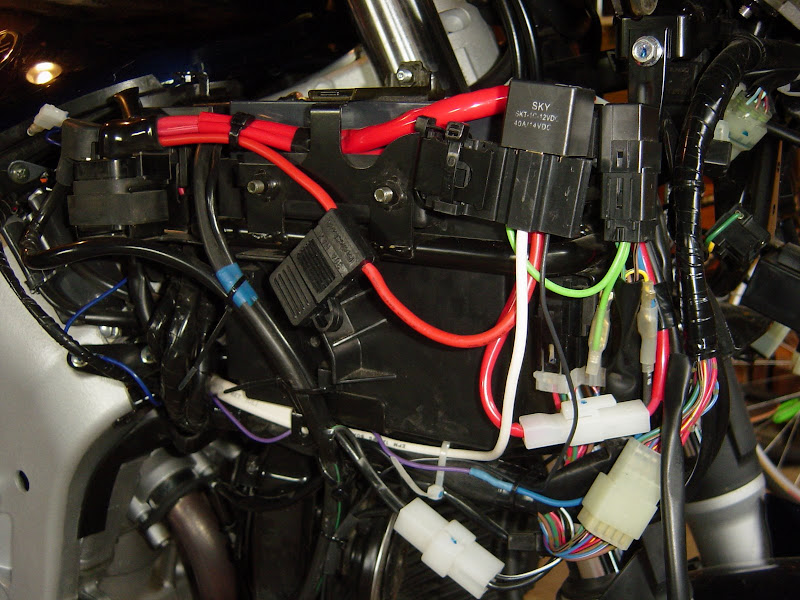
I'm adding a relay. I want to position it close to the battery and other relays.

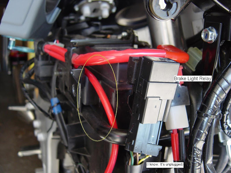
Here's the spot (circled in yellow):

DSC03809%20resized-n-marked%20up.JPG


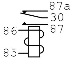
Here's my new relay and harness:

DSC03810%20resized.JPG


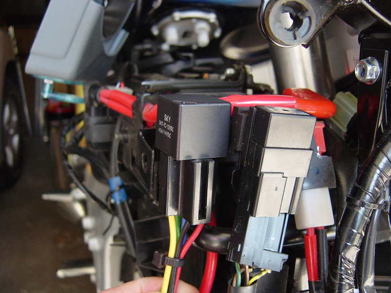
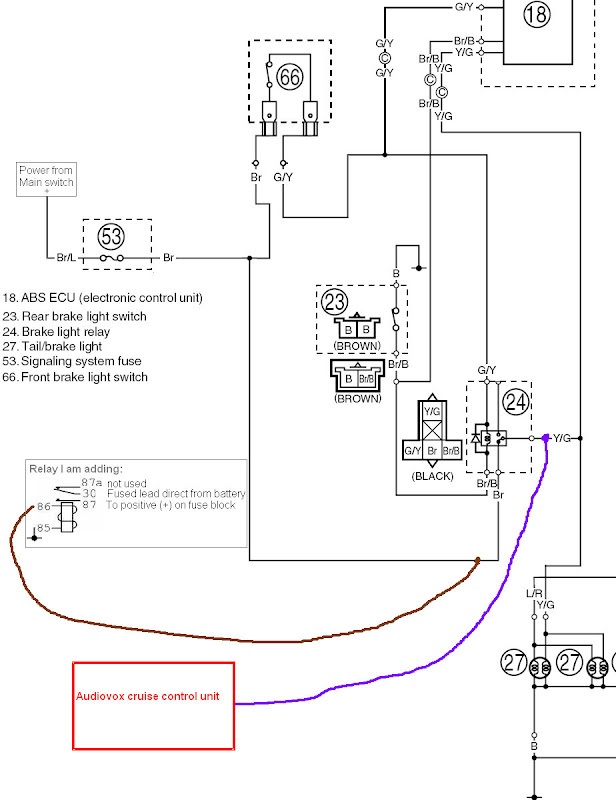
I want to use the power supply to the brake light relay (brown wire) as the switched power, or 86 pin on the relay that I'm adding. It seemed like a simple plan until I looked at the wiring diagram in the Service Manual. Both the front and the rear brake light switches are connected to this relay and the rear brake light switch goes to to ground. I don't see any problems with my plan, but the fact that I don't fully understand the circuit makes me a little nervous.

Then, I had this other idea that as long as I was messing with the brake light relay, I could use the Yellow/Green wire as the brake light connection on my AVCC.

I know how to release the female blade connectors from the harness, so the plan is to use blade tee connectors and heat shrink instead of tapping into the wires.

Please feel free to point out any problems with this plan.

 
It depends what you want to do and how much load you are going to have on that circuit.

What ever the load is most likely require a new circuit fused correctly correct wire size and proper grounding. Done in this manner you will eliminate electrical problems with incorrect wiring.

Start your new circuit from your battery on a new terminal junction made for this type of work

weekend rider :)

 
Let me try this again.

Here is the diagram for the relay I'm installing:

relay-diagram.jpg


Here's the diagram for the existing brake light relay:

Wiring%20diagram%202.jpg


The purple line is the purple wire from the AVCC.

The brown line is to the 86 pin on the relay I'm adding.

Please look this over and comment on it. I'm looking for a little constructive criticism. Also, if you feel especially generous explain how the existing brake relay works.

Thanks again,

Joe

 
Let me try this again.

Here is the diagram for the relay I'm installing:

relay-diagram.jpg


Here's the diagram for the existing brake light relay:

Wiring%20diagram%202.jpg


The purple line is the purple wire from the AVCC.

The brown line is to the 86 pin on the relay I'm adding.

Please look this over and comment on it. I'm looking for a little constructive criticism. Also, if you feel especially generous explain how the existing brake relay works.

Thanks again,

I don t know if this will help you .....

When you activate the brakes, this power up the coil of the relay ( 85 & 86 ), when the coil is activate it is creating a magnetic filed that will ''attract'' the contact (30 ) actually on 87a to go on 87.

This will bring voltage from the battery to go on the + of the fuse block.

When you release the brake, this shut off the magnetic field and contact # 30 will go back to the original position

Relay are use to drive high current to a circuit without having to use a big switch and big wiring. Using the relay a little switch could activate the relay, and the big current will flow thought it.

Hope this is the explanation you were looking for.
 
G/Y supplies power to the brake light relay, Br/B wires go to the brake light switches...which are in parrallel so either one of them will complete the circuit to ground. Once the circuit through the brake light relay is complete, it activates and supplies power to the brakelights by passing 12 through the relay on the Br wire to the Y/G. The other leg of the Y/G is used to give the ABS module a signal that you are braking.

 
Last edited by a moderator:
Relays are for taking the big amp dram when they are engaged, it takes the place of a switch. The wire will be the same size all the way trough the circuit, it has to carry the voltage and the amperage plus it reqired design safety for its current draw usually 125% of the rated load I.E. #14 wire 15 amps max amp draw 12 amps etc.

You should never splice into your brake wires running a control like abs because of the the following> you could blow a fuse,

to much current draw causing a heatng problem with the wire melting the insulation than going to ground blowing a fuse,or even melting a section of your wiring harness and not least could cause your bike to catch on fire. These are just some of the problems when one splices into another circuits wire.

As an example I often wonder if this is why the start switches fail, because of to much amperage going through the switch.

Heat is your worst enemy for electricity and it can happen in many forms in a circuit ruinning your day and your wallet.

weekend rider :)

 
Thanks for your comments.

Last night I was 95% sure of my plan, but this morning I'm not so sure. I have a couple of follow up questions.

Pierre,

I didn't think my relay was going to be activated by the brakes. I thought it would have a steady supply of voltage whenever the main switch is on.

P.S. Your avatar is on srike again and I miss her.

un4gvn,

It looked to me like one of the brake light switches was on the positive (equivalent to an 86 pin?) and the other brake light switch was on the ground (equivalent to an 85 pin?) Does that mean that the brake switches are normally "on"? So, instead of the switch powering something, or providing ground to something, these switches interupt that connection? It seems weird, but I can at least sort of understand if that is the case.

weekend rider,

When you write "You should never splice into your brake wires running a control like abs ..." are you telling me my plan is a bad one? I didn't think relays drew that much power. I thought I was just drawing a little power from the existing brow wire (poitive to front brake switch and positive to brake light relay) to activate my relay.

 
Joe,

I have no idea what the other guys are talking about. Your plan is a simple and correct way to accomplish what you desire.

The brown wires running from the fuse block will be hot (+12V) any time the ignition switch is on. That will energize your relay with the key switch. I'm assuming that you just did not show the rest of the wiring, where you run a new (fused) wire directly from your battery to the relay terminal 30, and then hook up the red power wires from the AVCC to terminal 87.

If it were me, I would also add a switch to your circuit so that you can manually disable the AVCC in case of a malfunction. I would put that switch in series with your brown wire (to de-energize the new relay) or if you don't use a relay, in series with the red power wire.

The Y/G wire will be hot only when one of the brakes is activated, which is exactly what the AVCC needs to "disengage" cruise when you brake. This is a signal only, so it will not effect how your brakes work.

Here is a web site that has some nice details about installing the AVCC. Some of the other web sites don't show the wiring all that clearly.

 
... I'm assuming that you just did not show the rest of the wiring, where you run a new (fused) wire directly from your battery to the relay terminal 30, and then hook up the red power wires from the AVCC to terminal 87.
That is shown, but in a very abbreviated form. Look under "Relay I'm adding" in the illustration. I just added text next to each pin number on the relay.

If it were me, I would also add a switch to your circuit so that you can manually disable the AVCC in case of a malfunction. I would put that switch in series with your brown wire (to de-energize the new relay) or if you don't use a relay, in series with the red power wire.
I was planning on powering the AVCC from a Blue Sea fuse block. This relay is going in first. It powers the fuse block, which powers the AVCC. So, if I want to manually disable the AVCC, I should add a switch between the fuse block and the AVCC key pad? The "off" button on the key pad won't do the job?

Here is a web site that has some nice details about installing the AVCC. Some of the other web sites don't show the wiring all that clearly.
Good one. I remember that one from a few years back, but I had forgotten it for this install. Thanks, that'll come in handy!

The FJR has a clutch switch. What do you think about somehow tying that into the brake/disengage signal to the AVCC.

:yahoo: I just got a call today that I'll be interviewing for a position I applied for in early March. :yahoo: This is turning out to be a great day. (I have to get back to work or I would find the exact quote from Romancing the Stone)

Thanks again

 
Good luck on your job interview. There are going to be many ways and many ideas on how to do it you have to choose the correct one.

Since I work in ths field electrical and most of my problems are from people taking short cuts not realizzing what the out come is. That is why they make fuse bocks so you can wire correctly with out damaging the rest of the equiment.

To be prudent err on the side of safety.

Others may disagree but that is their rite good lu

 
If it were me, I would also add a switch to your circuit so that you can manually disable the AVCC in case of a malfunction. I would put that switch in series with your brown wire (to de-energize the new relay) or if you don't use a relay, in series with the red power wire.
I was planning on powering the AVCC from a Blue Sea fuse block. This relay is going in first. It powers the fuse block, which powers the AVCC. So, if I want to manually disable the AVCC, I should add a switch between the fuse block and the AVCC key pad? The "off" button on the key pad won't do the job?
No, it really won't. There is no power switch in the switch pad really, just a button that sends a signal to shutdown the main unit. The switch pad is also the thing that seems to have the most weather related problems, so you don't want to have to rely on the signal from that switch pad being able to shut down the main unit.

The FJR has a clutch switch. What do you think about somehow tying that into the brake/disengage signal to the AVCC.
That is not so easy. The wiring logic of the clutch switch is a bit messy. It is wired in conjunction with the side stand switch and the neutral switch to enable /disable the engine and starter, so the voltage at the switch is not what we want all the time. It is unnecessary anyway as the CC has a feature where it will disengage if it sees a spike in rpm, such as would occur if you zoned out and pulled in the clutch during cruise. You enable that feature by pulling the jumper off next to the dip switches to tell the unit you have a manual transmission.

:yahoo: I just got a call today that I'll be interviewing for a position I applied for in early March. :yahoo: This is turning out to be a great day. (I have to get back to work or I would find the exact quote from Romancing the Stone)
Thanks again
Congrats , and good luck with the job.

 
Here's a photo of everything finished:


Sorry I don't have time to write a description for the photo, I have to pack for a trip.

If anyone wants to know more about my wiring, let me know. I'll add captions or text with arrows or something. (after June 9)

Oh yeah, for more detail, click on the photo. It's a link to the Picasa photo. After that, click "Download Photo"

 
Top