torch
Well-known member
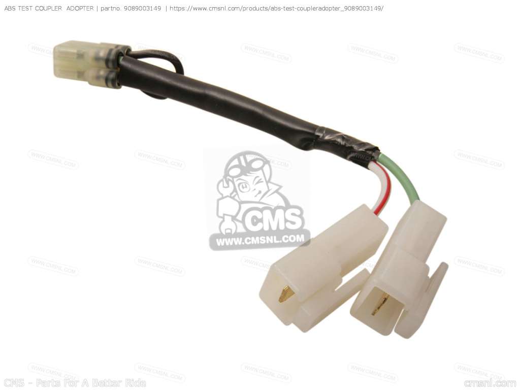
By now, everyone knows about the discontinued ABS test adapter and the jumper wire work-around. The OEM version looks like this (image shamelessly borrowed from the internet):

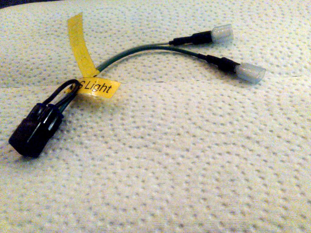
Now, I'm all for workarounds, but I'm also a tool junkie so I wanted the "correct" tool, just because. I sourced the correct style connector (cheap per unit, but had to buy 50 units) and made my own. Call it the Mark I:

I was curious about those two wires. Nobody ever seems to mention them. Digging into the FSM, I found the green wire is used to show "current" error codes by pulsing the ground. One is to connect an analog voltmeter to battery positive and ground the meter via the green wire. Fault codes can be decoded by counting the swings of the needle. The long duration pulses indicate 10's and are summed to find the left digit of the code. Short duration pulses follow and are summed to find the right digit. A long pause separates successive codes. EG: Two long pulses followed by five short pulses represent error code 25. Just like an old OBD 1 GM product.
It seems pointless, since the error codes are displayed in English right there on the dash in place of the odometer. But further reading revealed that engine error codes take precedence, preventing ABS error codes from being displayed, so in the unlikely event that the bike has stored ECU codes, this would be the only way to reveal an ABS code. Potentially useful, I suppose. Except that who the hell still uses analog volt meters? The only ones I have left are VTVMs (Vacuum Tube Volt Meter) that are powered from the mains. Museum pieces I only keep around for occasional high-voltage CRT power supply measurements.
The purpose of the white/red wire seems completely undocumented, however the wiring diagram shows it taps into the ABS light itself. A voltmeter (digital) shows voltage to ground when the light is on, and 0 volts when the light is off, which would seem to confirm the diagram. This seems even less useful, but I suppose it does provide a means to verify whether or not the ABS is sending a signal to the light vs the bulb is just burnt out without tearing apart the entire dash.
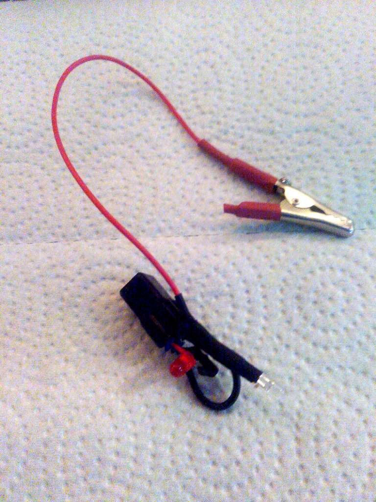
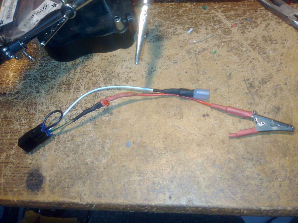
My next thought was "Gee, why not make it real easy and replace the analog meter with a pair of low-power LEDs? The battery is right there, I can replace two quick-connects with one alligator clip. And since I had 49 spare connectors, the Mark II was born:

In place of the green wire, a 680 ohm current limiting resistor (to [email protected]) was wired in series with a white LED and alligator clip The white/red wire was similarly replaced with a resistor/red LED combo wired to the ground provided for the jumper.
I was half-right. The green wire replacement works fine. The white/red wire replacement: not so much. Ok, yes it does come on when the ABS light should come on and flashes at the appropriate rate when the ABS light should be flashing -- that part works. But note that I said "when the ABS light should come on"; that was no error, the ABS light no longer works when that red LED is in circuit. But it gets worse: the error codes are no longer displayed on the dash or stored in memory and Test #2 will no longer run.
So the Mark III will revert to the white/red wire with quick connector, leaving the white diode with alligator clip lead. But I'm already thinking about a Mark IV (I'll still have 47 connectors left, remember? <lol>) -- maybe something along the lines of an Arduino with high-impedance MOSFETs on the input GPIO and an LCD display of the decoded flashes...

Now, I'm all for workarounds, but I'm also a tool junkie so I wanted the "correct" tool, just because. I sourced the correct style connector (cheap per unit, but had to buy 50 units) and made my own. Call it the Mark I:

I was curious about those two wires. Nobody ever seems to mention them. Digging into the FSM, I found the green wire is used to show "current" error codes by pulsing the ground. One is to connect an analog voltmeter to battery positive and ground the meter via the green wire. Fault codes can be decoded by counting the swings of the needle. The long duration pulses indicate 10's and are summed to find the left digit of the code. Short duration pulses follow and are summed to find the right digit. A long pause separates successive codes. EG: Two long pulses followed by five short pulses represent error code 25. Just like an old OBD 1 GM product.
It seems pointless, since the error codes are displayed in English right there on the dash in place of the odometer. But further reading revealed that engine error codes take precedence, preventing ABS error codes from being displayed, so in the unlikely event that the bike has stored ECU codes, this would be the only way to reveal an ABS code. Potentially useful, I suppose. Except that who the hell still uses analog volt meters? The only ones I have left are VTVMs (Vacuum Tube Volt Meter) that are powered from the mains. Museum pieces I only keep around for occasional high-voltage CRT power supply measurements.
The purpose of the white/red wire seems completely undocumented, however the wiring diagram shows it taps into the ABS light itself. A voltmeter (digital) shows voltage to ground when the light is on, and 0 volts when the light is off, which would seem to confirm the diagram. This seems even less useful, but I suppose it does provide a means to verify whether or not the ABS is sending a signal to the light vs the bulb is just burnt out without tearing apart the entire dash.
My next thought was "Gee, why not make it real easy and replace the analog meter with a pair of low-power LEDs? The battery is right there, I can replace two quick-connects with one alligator clip. And since I had 49 spare connectors, the Mark II was born:

In place of the green wire, a 680 ohm current limiting resistor (to [email protected]) was wired in series with a white LED and alligator clip The white/red wire was similarly replaced with a resistor/red LED combo wired to the ground provided for the jumper.
I was half-right. The green wire replacement works fine. The white/red wire replacement: not so much. Ok, yes it does come on when the ABS light should come on and flashes at the appropriate rate when the ABS light should be flashing -- that part works. But note that I said "when the ABS light should come on"; that was no error, the ABS light no longer works when that red LED is in circuit. But it gets worse: the error codes are no longer displayed on the dash or stored in memory and Test #2 will no longer run.
So the Mark III will revert to the white/red wire with quick connector, leaving the white diode with alligator clip lead. But I'm already thinking about a Mark IV (I'll still have 47 connectors left, remember? <lol>) -- maybe something along the lines of an Arduino with high-impedance MOSFETs on the input GPIO and an LCD display of the decoded flashes...


