Power draw from OEM grip warmers?

Yamaha FJR Motorcycle Forum

Help Support Yamaha FJR Motorcycle Forum:

This site may earn a commission from merchant affiliate links, including eBay, Amazon, and others.
A

Anthony

Guest
Does anybody know what the power draw is from the OEM Grip Warmers?

Also, is it safe to assume that they are a rheostat? I highly doubt that they use PWM.

 
Last edited:
Does anybody know what the power draw is from the OEM Grip Warmers?
Also, is it safe to assume that they are a rheostat? I highly doubt that they use PWM.
Don't know the power, but I would say sub-2 amps - I once made my own heated grips for my Trophy, they got much hotter than my FJR ones, and they were 2 amps.

I'm fairly sure the controller isn't a rheostat, it doesn't seem to get hot (at least, not that I've noticed, and I use mine a lot :cold: ). It's powered from the headlight relay, but has a line from the ECU; I expect that's the input that reduces power ...

When the vehicle is stopped or travelling at extremely low speeds (e.g., in traffic jams), the grip warmer temperature is lower than when travelling at higher speeds.
... which presumeably is to reduce the battery discharging when the alternator is not turning fast enough. That wouldn't work with a rheostat (always assuming they don't mean the heat will be lower simply because the battery voltage is lower, in which case why have a line from the ECU?).

 
I've measured the Gen I OEM grips and controller on a test bench and the system never drew more than 2.5 amps at 14.5 volts. The Gen I and Gen II share the same 4 Ω total (2 + 2) grips. They both definitely use a PWM controller; I have the scope screen shots some place.

Just as a side note, after looking at several OEM PWM controllers, some are capable of driving a total straight ignition voltage DC level and others only drive ~98% with some very narrow pulse spikes remaining.

 
Last edited by a moderator:
Just as a side note, after looking at several OEM PWM controllers, some are capable of driving a total straight ignition voltage DC level and others only drive ~98% with some very narrow pulse spikes remaining.

Can you interpret this into lay persons lingo?

 
Just as a side note, after looking at several OEM PWM controllers, some are capable of driving a total straight ignition voltage DC level and others only drive ~98% with some very narrow pulse spikes remaining.

Can you interpret this into lay persons lingo?
"Lay person" my ass! A lay person gets it already.

Alan, 'splain it so us dumbshits unnerstanz!

 
QUOTE (RadioHowie @ Mar 11 2010, 03:59 AM) <{POST_SNAPBACK}>

QUOTE (Anthony @ Mar 10 2010, 07:58 PM) <{POST_SNAPBACK}>

QUOTE (ionbeam @ Mar 10 2010, 01:14 PM) <{POST_SNAPBACK}>

Just as a side note, after looking at several OEM PWM controllers, some are capable of driving a total straight ignition voltage DC level and others only drive ~98% with some very narrow pulse spikes remaining.

Can you interpret this into lay persons lingo?

"Lay person" my ass! A lay person gets it already.

Alan, 'splain it so us dumbshits unnerstanz!

Perhaps this might help?

SwitchMode.jpg


Anyway, someone who can rebuild a dead FJR can't be a complete "dumbshit". There must be some intelligence in there somewhere.

[Edit] This is a (simplified) citcuit diagram.

GripCircuit.jpg


Last edited by a moderator:
Thanks, Mr. Trophy.....

This image 'splained it all to me. Had Alan come right out and written "Pulse Width Modulator" instead of PWM, I would have understood the rest of his sentence, but all this acronym BS gets me confuzzled at times.

I mean really, if it was Bustanut, I would have thought he meant "Posting While Masturbating".

 
OK, I'll take a stab, full on or 2% less than that, then all the way down to off. ;)

 
Last edited by a moderator:
That schematic is not quite right. The power to the heating elements is supplied from the circuit powering the brake lights, horns, glove box latch, etc. The controller switches the unfused ground or return circuit. The headlight relay output just switches the controller on and off -- energizes the controller circuitry. The ECU pulses the controller based on road speed -- you need more heat with more air flowing across the hands.

 
That schematic is not quite right. The power to the heating elements is supplied from the circuit powering the brake lights, horns, glove box latch, etc. The controller switches the unfused ground or return circuit. The headlight relay output just switches the controller on and off -- energizes the controller circuitry. The ECU pulses the controller based on road speed -- you need more heat with more air flowing across the hands.
I stand corrected :mellow: (I drew the circuit from memory), but I think the principle is correct.

 
Being the complete electrical idiot that I am, I had my PIAA 1100's installed by a guy at a local bike shop. So please pardom my ignorance with this question.

When the guy installed the PIAA toggle switch he put it on the panel along with the grip warmer switch. In the process he tied into the grip warmer switch to power the PIAA's. While out of town on a ride, it was a cool evening and I had the grip warmers on, I noticed that evening that the PIAA's were not working. Thinking I just had a wiring issue I resolved to call him about it the following week when I returned home. A couple of days later, I discovered that the PIAA's were working again. I finally determined that if I turned the grip warmer switch past about half way then it draws too much power and the PIAA's turn off. If I turn the grip warmers down then the PIAA's come back on. Obviously, all of this is with the PIAA toggle switch in the "on" position.

So, my question is this, other than the fact that the PIAA's don't work when the grip warmers are turned up to 50%+, are there any other (electrical) issues I should be concerned with? I note that someone mentioned the brake lights are on the same circuit. I haven't checked, but will when I get home, to see if the brake lights also turn off when the PIAA lights are turned on and the grip warmers are on. Obviously, this would be a problem that needs to be addressed. Any assistance would be appreciated.

 
Last edited by a moderator:
QUOTE (FJRBandit @ Mar 11 2010, 10:14 PM) <{POST_SNAPBACK}>

...

When the guy installed the PIAA toggle switch he put it on the panel along with the grip warmer switch. In the process he tied into the grip warmer switch to power the PIAA's. ...I finally determined that if I turned the grip warmer switch past about half way then it draws too much power and the PIAA's turn off. If I turn the grip warmers down then the PIAA's come back on. Obviously, all of this is with the PIAA toggle switch in the "on" position.

So, my question is this, other than the fact that the PIAA's don't work when the grip warmers are turned up to 50%+, are there any other (electrical) issues I should be concerned with? I note that someone mentioned the brake lights are on the same circuit. I haven't checked, but will when I get home, to see if the brake lights also turn off when the PIAA lights are turned on and the grip warmers are on. Obviously, this would be a problem that needs to be addressed. Any assistance would be appreciated.

Ok, here we go.

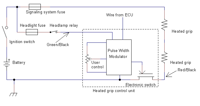
Firstly, here is a diagram of the original grip warmer circuit that I believe to be correct (ConstantMesh will hopefully correct me if this is wrong):

SwitchMode2.jpg


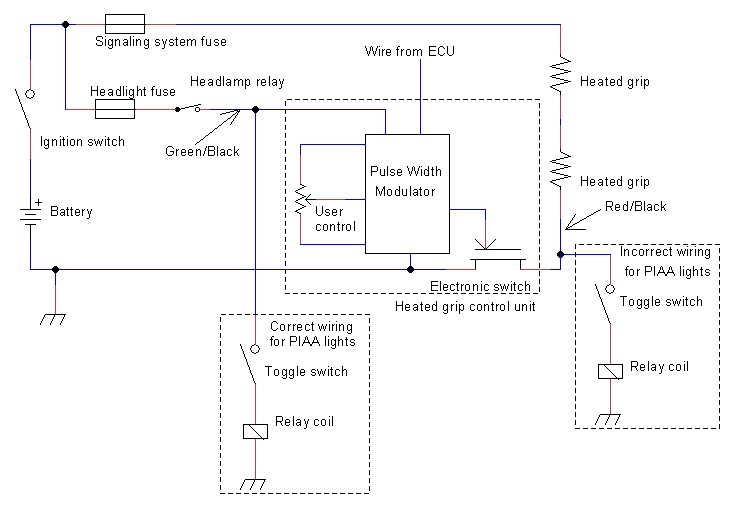
Assuming this is correct, I suspect your installer made a slight error in his wiring to the grip controller. I assume he wired a switch from the red/black wire to your toggle switch, then to a relay coil, the other side of the relay coil going to ground, the lights being powered throught the relay contacts from the battery (hopefully fused).

If this is what he did, then the effect will be that with the grip heaters off or on a low setting, the relay coil will get sufficient power through the grip heaters to turn on. As the grip control is turned up, the effective voltage on the relay coil will reduce, so that the relay will turn off.

It will not affect any other circuit, so brake lights etc will work as normal.

The correct wire to use for the relay would be the green/black wire, see diagram below.

WrongPIAA.jpg


If I'm right (a rare event for me, but you never know
blink.gif
), with the suggested change, the PIAA lamps would also behave like the headlights so that they won't turn on until the engine is running.

As an aside, the ground wires from the new light circuit should go back to the battery so as not to put extra load on any of those nasty earth connectors.

 
Last edited by a moderator:
If this is what he did, then the effect will be that with the grip heaters off or on a low setting, the relay coil will get sufficient power through the grip heaters to turn on. As the grip control is turned up, the effective voltage on the relay coil will reduce, so that the relay will turn off.
You hit the nail on the head mcatrophy. Thanks for the info and taking the time to draw the schematics, albeit "Greek" to me. I'll print it out and let my installer straighten it out.

This is what makes this forum so awesome! People sharing knowledge from their specific areas of interest with others, like me in this particular instance, that have not a clue what the hell they're talking about. Now, on the other hand, if you want to discuss beer or babes, then dial me up! :yahoo:

Thanks again for all of the help!

 
Top