ionbeam
2 FUN
This project is rated 3 out of 5 for difficulty


========================================
Parts:
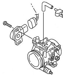
Yamaha TPS P/N 5PS-85885-01-00 for both Gen 1 and Gen 2 FJRs
Location on the FJR:
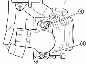
The TPS is on the cylinder #4 end of the throttle body rack.


The bottom screw has limited access because it is located right next to the frame. But for this screw the TPS replacement would be quick and simple.
Tools:
T25 tamper resistant Torx bit a.k.a. security Torx bit with an offset ratchet driver wrench

--or-- you can buy a T25 Torx wrench that is available with different arm lengths, you need a very short arm for this job. You can buy this too here.

12mm socket, Tank pivot bolt
10mm socket, Tank screws by steering stem
4mm wrench, Body work, Allen head screws,
Allen wrench, screw that hold the rubber shield to the tee bar
A multi-meter would be very helpful but not absolutely required
Prepare:
Begin Replacement:


========================================
Parts:
Yamaha TPS P/N 5PS-85885-01-00 for both Gen 1 and Gen 2 FJRs
Location on the FJR:
The TPS is on the cylinder #4 end of the throttle body rack.


The bottom screw has limited access because it is located right next to the frame. But for this screw the TPS replacement would be quick and simple.
Tools:
T25 tamper resistant Torx bit a.k.a. security Torx bit with an offset ratchet driver wrench

--or-- you can buy a T25 Torx wrench that is available with different arm lengths, you need a very short arm for this job. You can buy this too here.

12mm socket, Tank pivot bolt
10mm socket, Tank screws by steering stem
4mm wrench, Body work, Allen head screws,
Allen wrench, screw that hold the rubber shield to the tee bar
A multi-meter would be very helpful but not absolutely required
Prepare:
- I'm not going into the whole tank removal because it has already been done very well here at FJRTech:
- Reminder: Unclip two hoses from the left side of the tank
- Raise and prop tank leaving all hoses and wires connected if possible
- Remove rubber cover from Tee Bar
- Move wires out of the way from TPS -- O2 wires are in this area
- Unplug TPS connector by pressing down on the tab on the connector -- DO NOT pull on the wires
- I put a shop towel under the TPS to catch screws and tools as I repeatedly drop them
- I used a short step ladder, clipped my trouble light to the top tread -- aimed at the work site, used the other treads as a tools and parts trays handy to my work site
- Chair to sit comfortably
- Relax, plan to go slow
Begin Replacement:
- Remove bottom screw from the TPS while you are still fresh and cheerful
- Remove top screw from the TPS
- Pull the bad TPS off, it should come off freely
- Be sure that the rubber shaft seal came off with the old TPS, view new TPS and compare
- Gently push on new TPS trying to align the center with the rectangular post on the throttle body rail
- Twist the new TPS against the internal spring until the slots align with the screw holes
- Install lower screw just enough to stop any looseness but do not tighten
- Install upper screw just enough to stop any looseness but do not tighten
- Follow FSM procedure to electrically align the TPS
- My results which should work for you too:Rotate the TPS until the multi-meter reads ~650 ohms and lightly tighten so that the TPS won't move when the throttle is rotated
- invoke the diAG screen and check diAG code 01. How-To is here. (Post #3)
- verify TPS reading is within spec per FSM (15-17 closed and 97 to 100 open) mine read: throttle closed 15; throttle wide open 98-99 when the resistance was set to 650 ohms (bad TPS was set to 620 ohms yielding 14 to 97)
- tighten the two TPS screws, confirm via diAG that you are still in spec
- verify hoses & wires are clear of moving parts and still attached, start engine
- confirm idle speed; confirm engine runs smoothly and linearly follows TPS. You may need to tweak the idle speed.
- you may want to mark the top screw with a line across it to the TPS body so you that can visually verify that the TPS adjustment hasn't moved should you want to check it at some later time
- use Locktite blue on the rubber cover screw; seems like overkill but it's Yamaha's way
- sprits the left side rubber wellnut and rubber hose holder with a good silicon spray to facilitate reconnection
- reassemble
- road test to confirm it works when hot
- done, beverage of choice
Last edited by a moderator:


