BwanaDik
Well-known member
This is yet another install thread, however, like with the previous Penske and fork installs, I’ve done a few things differently and have tried to consolidate some of the links and part numbers.
Between Brodie and my mechanic, Dan, up at Cycle Shack, you guys put the wiring installation bar pretty high. So I had to really do a really professional job. I made up a wiring diagram before starting because I was basically making a new complete harness and it helped a lot. I ordered several different colors of wire from Grainger so the whole thing wouldn’t be just black and red. I found out later you can now buy multicolored wire from Parts Unlimited at most motorcycle shops.
I got a full Soltek kit, including the diffusion lens and lens covers, from another Forum member, brand new and still in the box. Plus the cool brackets from the Unmentionable One. I also sprung for the Fuzeblock distribution block because I like the built in relay and the ability to change from switched to un-switched by merely moving the fuse.
I used the same switch as seen Here . You buy them Switch but unfortunately they don’t sell the little plastic covers. Go figure. I got some from another Forum member (thanks George) so if you need a couple, I have plenty. Here is another good thread for reference.
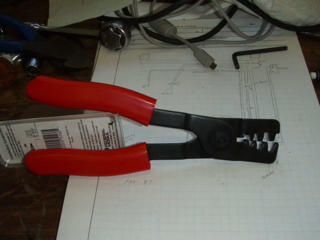
I also used THESE connectors for all wiring connections. Actually, I originally bought some connectors from the shop that are listed as Honda connectors, before I found these. They are way better than anything you can get at NAPA or The Zone. It's quite an assembly procedure because you have to fit 4 pieces for each connection but they are water tight and very secure. I also got the crimping tool from the same place, it’s WAY better than any other crimping tool I’ve ever found and it appears to be the one needed for these connectors
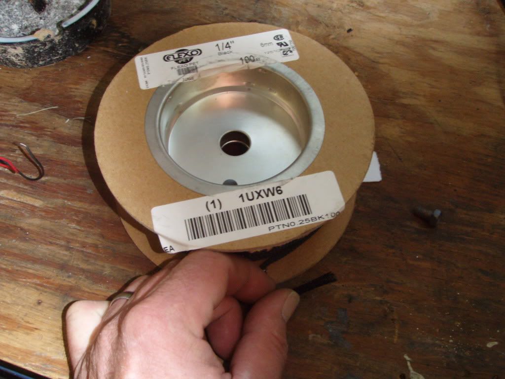
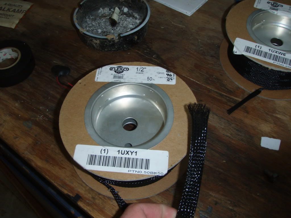
I found this wire loom at Grainger Clicky It’s really cool looking, almost like fishnet stockings (Odot will probably have his whole bike rewired with this stuff by next SFO). A couple of drawbacks: 1) You have to pull all of the wires in the harness thru at once, it’s difficult to thread another wire thru if there is already a bundle inside. Not like the corrugated plastic ones where you can feed a new wire in thru the split. 2) The ends fray badly when you cut the loom to length. It is easily fixed with electrical tape but I wonder at the long term life of the tape out in the weather.
The routing of the wiring was a little tricky inside the left switch but
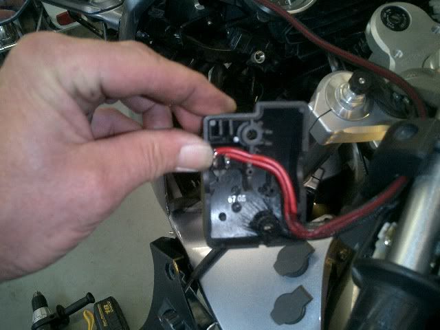
after re-reading This a couple of times and looking at the pictures, I figured it out. It's not an easy fix as there is almost no room inside the switch cover. I had to cut off the ends of the rocker switch connectors to clear the handlebar and solder the wires onto the connectors. I was able to run the switch wire down the handle bar inside the fishnet loom and into the harness connection behind the B/C panels
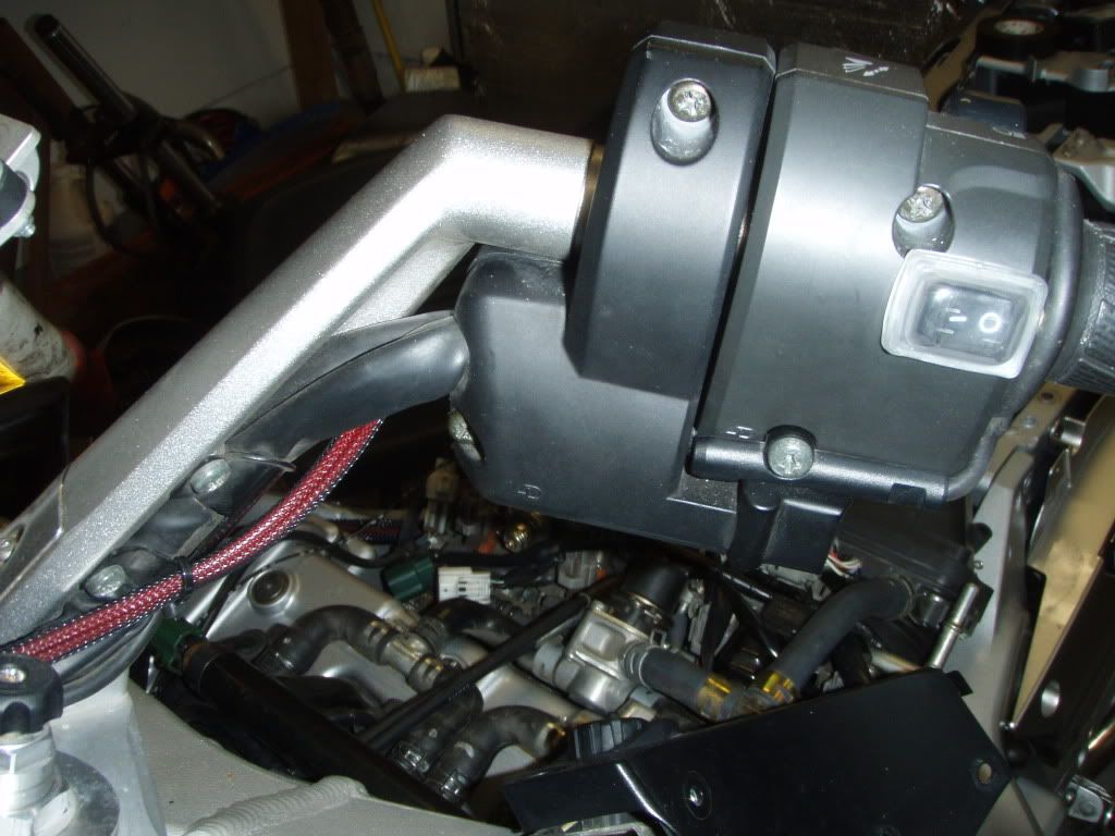
You can see the main 30 amp fuse holder for the Fuzeblock in this picture too.
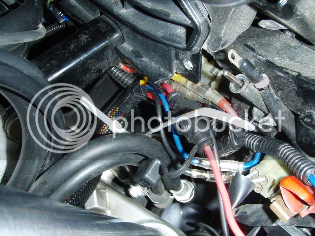
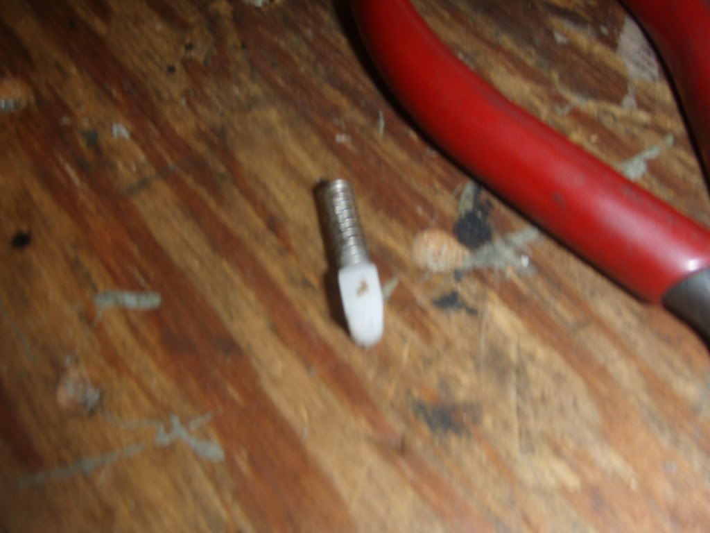
Unfortunately, during the switch installation, I stupidly took the plate off the bottom of the AE hand shifter and return springs fell out (picture). I found one of them but the other is lost in the bowels of the bike (I think). Oh well, I never use the hand shifter anyway. If you see any of these laying around, I'd be happy to take them off your hands
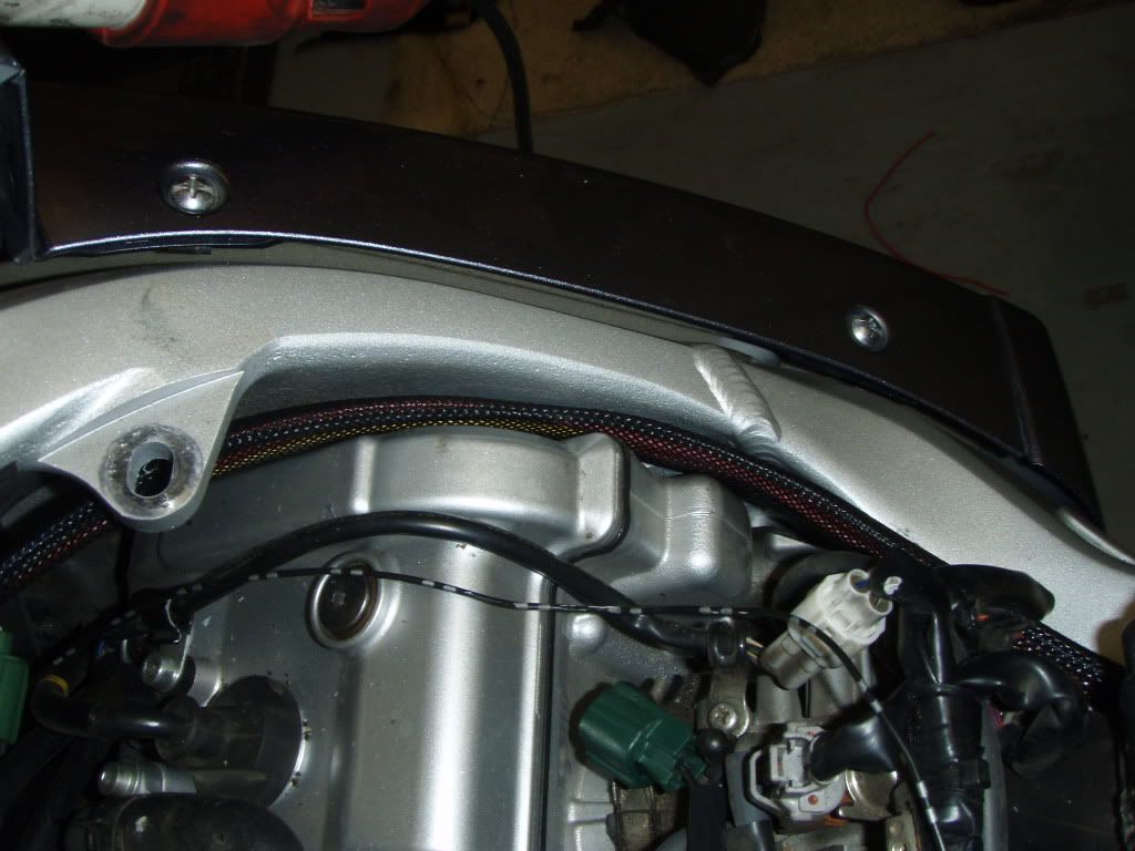
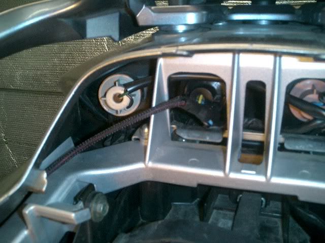
The wiring to the front of the bike included power for the Soltek’s, two Powerlets, the switch wires, and the main feed from the battery to the Fuzeblock (including all grounds back to the Fuzeblock). I connected the Soltek handswitch to one of the "switched" circuts in the Fuzeblock to trigger the Soltek relay (NAPA P/N AR272 25amp/12 volt). I ran it thru the headset and along the inner frame rail
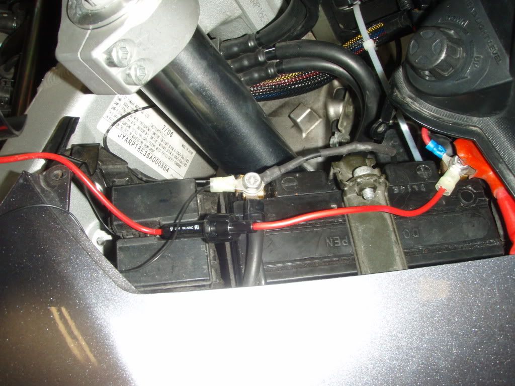
I also, since I was in there, re-wired my Datel with sensible sized wiring and an inline fuse.
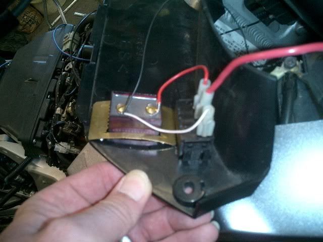
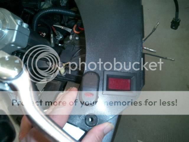
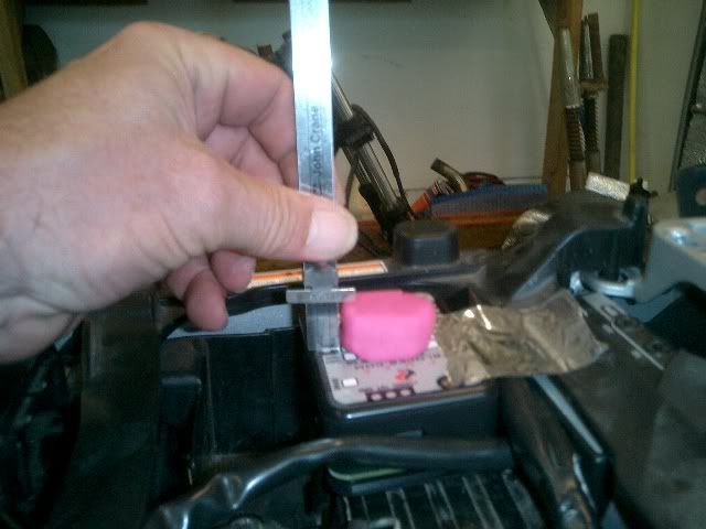
I mounted the Fuzeblock on top of the AE shift control unit. Unfortunately the control unit takes up a lot of the tool box area but it seemed like a good location. I also did a clearance check with some Play-Doh to be sure it all fit under the seat.
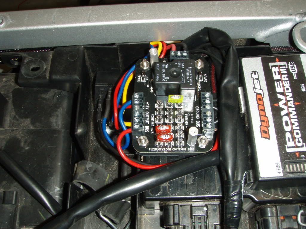
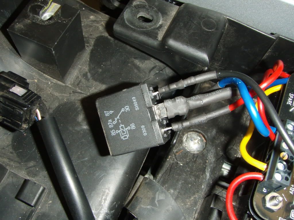
Another thing I didn't like was how the connectors didn't seat all the way down on the Soltek relay. Obviously, the answer is to get the correct size plugs but they'd have to be pretty long. Any one else have this problem? Do you cut off some of the blades on the relay?
I took the “switched” power off the tail light wiring, as mentioned in other install posts. However, the wiring loom over the tail assembly wiring is tough to get thru so I ended up taking apart the tail assembly to get to the wiring. I used Posi-lock connectors to tap into it. I’m still not real happy with the way it ended up but it’s probably OK. I later moved the wire behind the strut. I also dumped the Posi-lok and did a proper splice with the four piece connectors listed at the top. The Posi-lok's seem to split the 16 and 18 gauge wires and not necessarily make a solid connection.
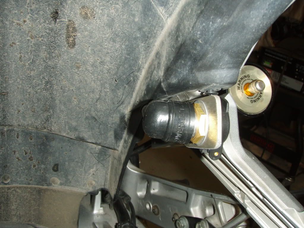
I also put a Powerlet behind the Penske mount so Bambi can plug in her vest if she needs to. I may also use it for a future aux. fuel cell I have in mind.
After I got everything installed and buttoned up, my turn signals didn’t work. Turns out that somehow the little plate inside the hand switch had come adrift and the clip that holds it in place was gone. Don’t know how that happened as I hadn’t touched it but I was able to fix it with a zip tie. May be a warrantee thing, have to check with the shop. Odd.
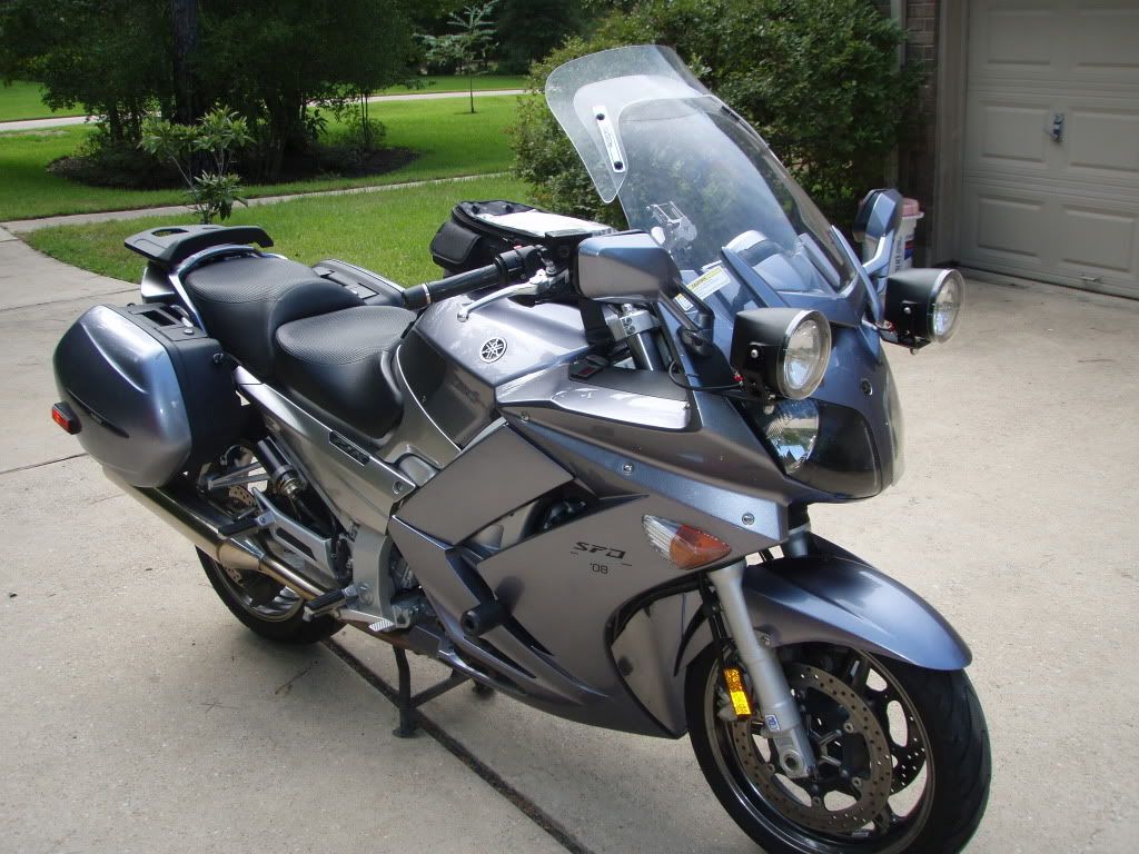
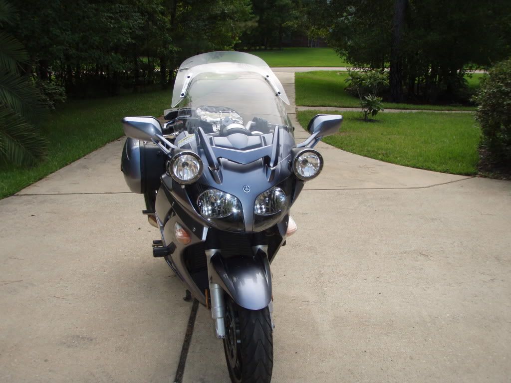
Here’s the finished install. I like the look of the black bezels better than the “rubbed red nipple” look of, say, Carvers bike. I think it looks “Factory”. Each to his own.
It took me several weeks to do the whole thing, mostly because at each step I'd discover some new really cool way to do something so I'd have to wait for the UPS man to deliver it. The whole install would have only taken a day if I had the necessary parts on hand. So if you do something like this, go thru the links above, draw up a wiring diagram and make a complete list of everything you need before you start. Luckily it was too hot to ride here for July/August so it was no big deal.
Between Brodie and my mechanic, Dan, up at Cycle Shack, you guys put the wiring installation bar pretty high. So I had to really do a really professional job. I made up a wiring diagram before starting because I was basically making a new complete harness and it helped a lot. I ordered several different colors of wire from Grainger so the whole thing wouldn’t be just black and red. I found out later you can now buy multicolored wire from Parts Unlimited at most motorcycle shops.
I got a full Soltek kit, including the diffusion lens and lens covers, from another Forum member, brand new and still in the box. Plus the cool brackets from the Unmentionable One. I also sprung for the Fuzeblock distribution block because I like the built in relay and the ability to change from switched to un-switched by merely moving the fuse.
I used the same switch as seen Here . You buy them Switch but unfortunately they don’t sell the little plastic covers. Go figure. I got some from another Forum member (thanks George) so if you need a couple, I have plenty. Here is another good thread for reference.
I also used THESE connectors for all wiring connections. Actually, I originally bought some connectors from the shop that are listed as Honda connectors, before I found these. They are way better than anything you can get at NAPA or The Zone. It's quite an assembly procedure because you have to fit 4 pieces for each connection but they are water tight and very secure. I also got the crimping tool from the same place, it’s WAY better than any other crimping tool I’ve ever found and it appears to be the one needed for these connectors

I found this wire loom at Grainger Clicky It’s really cool looking, almost like fishnet stockings (Odot will probably have his whole bike rewired with this stuff by next SFO). A couple of drawbacks: 1) You have to pull all of the wires in the harness thru at once, it’s difficult to thread another wire thru if there is already a bundle inside. Not like the corrugated plastic ones where you can feed a new wire in thru the split. 2) The ends fray badly when you cut the loom to length. It is easily fixed with electrical tape but I wonder at the long term life of the tape out in the weather.


The routing of the wiring was a little tricky inside the left switch but

after re-reading This a couple of times and looking at the pictures, I figured it out. It's not an easy fix as there is almost no room inside the switch cover. I had to cut off the ends of the rocker switch connectors to clear the handlebar and solder the wires onto the connectors. I was able to run the switch wire down the handle bar inside the fishnet loom and into the harness connection behind the B/C panels

You can see the main 30 amp fuse holder for the Fuzeblock in this picture too.

Unfortunately, during the switch installation, I stupidly took the plate off the bottom of the AE hand shifter and return springs fell out (picture). I found one of them but the other is lost in the bowels of the bike (I think). Oh well, I never use the hand shifter anyway. If you see any of these laying around, I'd be happy to take them off your hands

The wiring to the front of the bike included power for the Soltek’s, two Powerlets, the switch wires, and the main feed from the battery to the Fuzeblock (including all grounds back to the Fuzeblock). I connected the Soltek handswitch to one of the "switched" circuts in the Fuzeblock to trigger the Soltek relay (NAPA P/N AR272 25amp/12 volt). I ran it thru the headset and along the inner frame rail

I also, since I was in there, re-wired my Datel with sensible sized wiring and an inline fuse.


I mounted the Fuzeblock on top of the AE shift control unit. Unfortunately the control unit takes up a lot of the tool box area but it seemed like a good location. I also did a clearance check with some Play-Doh to be sure it all fit under the seat.


Another thing I didn't like was how the connectors didn't seat all the way down on the Soltek relay. Obviously, the answer is to get the correct size plugs but they'd have to be pretty long. Any one else have this problem? Do you cut off some of the blades on the relay?

I took the “switched” power off the tail light wiring, as mentioned in other install posts. However, the wiring loom over the tail assembly wiring is tough to get thru so I ended up taking apart the tail assembly to get to the wiring. I used Posi-lock connectors to tap into it. I’m still not real happy with the way it ended up but it’s probably OK. I later moved the wire behind the strut. I also dumped the Posi-lok and did a proper splice with the four piece connectors listed at the top. The Posi-lok's seem to split the 16 and 18 gauge wires and not necessarily make a solid connection.

I also put a Powerlet behind the Penske mount so Bambi can plug in her vest if she needs to. I may also use it for a future aux. fuel cell I have in mind.

After I got everything installed and buttoned up, my turn signals didn’t work. Turns out that somehow the little plate inside the hand switch had come adrift and the clip that holds it in place was gone. Don’t know how that happened as I hadn’t touched it but I was able to fix it with a zip tie. May be a warrantee thing, have to check with the shop. Odd.
Here’s the finished install. I like the look of the black bezels better than the “rubbed red nipple” look of, say, Carvers bike. I think it looks “Factory”. Each to his own.


It took me several weeks to do the whole thing, mostly because at each step I'd discover some new really cool way to do something so I'd have to wait for the UPS man to deliver it. The whole install would have only taken a day if I had the necessary parts on hand. So if you do something like this, go thru the links above, draw up a wiring diagram and make a complete list of everything you need before you start. Luckily it was too hot to ride here for July/August so it was no big deal.
Last edited by a moderator:


