Speed signal on instrument cluster

Yamaha FJR Motorcycle Forum

Help Support Yamaha FJR Motorcycle Forum:

This site may earn a commission from merchant affiliate links, including eBay, Amazon, and others.

obelix

Well-known member
Joined
Jun 5, 2009
Messages
48
Reaction score
0
Location
Luxembourg/Europe
I bought a gear indicator for the GenI FJR. My problem is that it wants to be connected to the +12V speedometer signal.

From the wiring diagram I can't see which one is the correct wire to tap into. So if anyone of the Gurus here could help I'd be most grateful.

If you wish I can post this part of the wiring diagram. Not that it does help much. Taking the signal at the sensor is not a good idea as it's pretty close to 5V, not 12V.

 
Unfortunately I don't think the Gen 1 has the kind of signal the gear indicator is looking for.

I remember when I had a VFR it would work because the VFR has a digital Speedo.

R

 
Acumen? Digi? GIPro? (Other?)

Posting the wiring diagram would be a real help. Most of the gear indicators just need a pulse stream that tracks the engine speed. You can probably use the crank angle sensor or one of the coil signal wires.

 
My '03 had one on it when I bought it, but it had died from water intrusion, the display was all fogged and had missing segments. I bought a replacement and tapped to his same wires, ez as pie.

He had tapped in at the ECU connector, I can't tell the wires without some digging. Basically it needs speed, tach, switched power, and ground, and there's a wire left loose, you ground it to go into programming mode. Sound like what you've got?

 
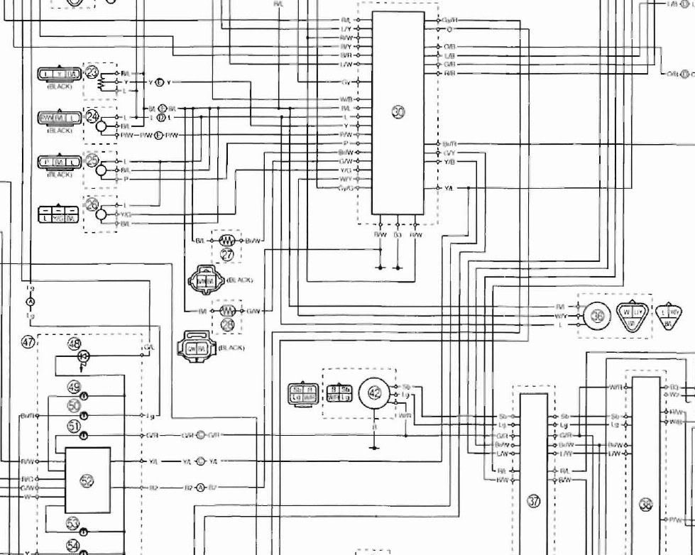
Here's the diagram from my FJR

Elec_diagr.jpg


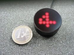
The unit is below, it's called Sureshift

Sureshift.jpg


It needs connection to +, ground, neutral, tach and speed signal. The first ones are easy, I just need to connect it to the speed input. The Yamaha uses an electronic speedometer as I didn't see a mechanical cable going up (did not remove the unit yet but I'm pretty sure on this.)

Learning is done with a simple ground wire.

Any help is welcome. I believe most cruise controls are connected the same way so I'm probably not the first to come to this problem.

 
Actually, the wiring information I was looking for was for your gear indicator.

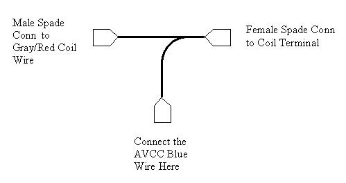
In any case, I went to the web site for the SureShift and they clearly state that you can use the coil trigger circuit in place of the speedometer. You can use either the solid Orange wire or the Gray/Red wire that signals the coils. You can tap either one of these wires right at the coil or at the ECU. While the ECU connector is fairly accessible you can make a neater job of it by going to the coil. Use three crimp spade connectors and make a Tee tap that connects to the coil, using the Tee part to connect to the SureShift. I've got a drawing for the Tee someplace; I made it for my Audiovox cruise control.

Edit to add:

CoilTee.jpg


You would connect the SureShift speedo sensor to what I call the AVCC Blue Wire spade connector in this drawing.

 
Last edited by a moderator:
Thanks ionbeam

Didn't understand it that way. I thought the speed signal was mandatory.

However I noticed the speed signal input may be +5 to +12V which should match the FJR (think I saw 4.8V somewhere)

I'll give it a shot.

Thanks for your help.

 
From the web site:

Should there be no electronic speedometer or there is no suitable signal, a complete speedometer kit can be ordered from motogadget. It contains a very small reed contact (M5) with 150 cm connecting cable, two small neodymium magnets and an epoxy glue.

The coils will substitute for a tach pickup, though it will be 1/2 the speed of a tach (same range as a Hardley). The web site is offering a magnetic pickup kit to create a substitute for lack of a speedometer signal. The kit will most likely have you glue the magnets to the brake rotor, then affix the pickup to either the rear swing arm or front fork. In Warchild's FJR Tech site, the Sigma Cyclometer install shows one way to mount the magnets and sensor, it may be useful for ideas.

--------

All the up-link signals from the ECU to the Meter Assembly (here after MA) is done through a single wire that carries a serial digital signal. The data bursts will contain an address that the MA will use to route the data to the correct device in the MA; this is then followed by data for the device. This is how the speedometer is driven, by a digital data stream from the ECU. Based on a software priority list the ECU will update all the MA devices, in a never ending loop. The data updates happen so quickly you never see any gaps or pauses. The first turn-on sweep of the gauges is actually the ECU driving all the MA devices and confirming communications. On the Gen II bikes the ECU can issue error codes Er-1 to Er-4 that indicate various communication issues with the ECU.

 
Last edited by a moderator:
Alan, when they talk about the coil pickup, they're talking about picking up the tach signal, not the speed signal. They say you can use the coil instead of the tach for installations with "electronic tachometer." It still needs a speed pickup somewhere, because that's how it knows the gear you're in, by comparing the engine speed with the road speed.

Your connection will work perfectly for him for the tach signal, but not as a substitute for the speed signal. Gear indicator has to know the road speed, unlike a cruise control where you assume top gear is in use.

 
Last edited by a moderator:
Alan, when they talk about the coil pickup, they're talking about picking up the tach signal, not the speed signal...Gear indicator has to know the road speed, unlaike a cruise control where you assume top gear is in use.
Covered in the post just above your clarification. Thanks for pointing this out, I was working on it.

 
Yeah, that simultaneous typing thing.

I think mine is connected at the ECU for: speed sensor, tach signal, neutral switch, power, and ground. His doesn't seem to know about neutral. I believe my speed pickup is the speed sensor input to the ECU.

 
Hi wfooshee

Mine needs to be connected to the neutral signal too but that signal is the least problem.

If ionbeam is right the signal from speed sensor to ECU and from ECU to display is coded and not useable for this purpose.

I'm not eager to glue a magnet to the brake disc, just imagine it coming loose at top speed as Murphys law states.

 
Our Gen I FJR's VSS (Vehicle Speed Sensor) signal comes off the back-rear of the engine. The pickup reads the teeth of a gear in the transmission and produces a high switch rate signal which is too fast for some farkles to use, such as the Audiovox Cruise. If you want to try the VSS as your speedometer signal it is the White/Yellow wire at the ECU connector. The VSS is powered by a highly stable +5 reference voltage from the ECU so the VSS signal returned to the ECU toggle right around 5 volts & ground.

wfooshee says that he has his gear indicator connected to a 'speedometer' wire at this ECU so it would almost have to be the VSS wire. Since his gear indicator is a different brand than yours his *may* read the speedometer signal differently than yours. No way to know unless you try. If it works, great! If it doesn't work then it's back to the magnets & pick-up.

In the FJR Tech article they embedded the magnet into the Allen wrench socket of a hex screw to assist in holding the magnet in place.

 
Last edited by a moderator:
Looking at this article on fjr1300.info and refering to the wiring diagram, The speed signal is on the white wire (yellow stripe) and the tach signal is on the gray wire (red stripe) in the ECU harness. The neutral switch is on the light green wire in the other bundle. It doesn't go to the ECU, but it's nearby, on its way to the starter cut-off relay under the seat. I would pick up 12 volts and ground at the battery (or better yet, a fuse box,) not the ECU as done in the article (and incidentally on my bike by the previous owner) and that would leave just the three wires to route down to the ECU. Well, thinking about it you should probably even get tach and neutral up in the nose. The ignition coil has the gray/red wire, and the neutral wire (light green) goes into the instrument panel for the neutral light. (The neutral wire might be harder to reach in the nose, I haven't looked for it up there.) That leaves only the speed sensor to run down to the ECU area.

Regardless of the tap location, you want to leave a connector somewhere so stuff can easily come off the bike. Having to cut wires later on because you didn't think of it really sucks.

Six wires all together: speed, tach, neutral, battery, ground, and the training wire, tied up somewhere for daily use and not connected.

 
Last edited by a moderator:
This is just what I was looking for. I will give it a shot as soon as the bike is assembled again - changed to a different steering bar and now the bike is allapart. As soon as it shows any signs of live I will try this out and keep you posted.

Thanks

 
Top