Trigger Wire for Fuzeblock on '16 ES

Yamaha FJR Motorcycle Forum

Help Support Yamaha FJR Motorcycle Forum:

This site may earn a commission from merchant affiliate links, including eBay, Amazon, and others.

ElectricFJR

Well-known member
Joined
Aug 4, 2005
Messages
196
Reaction score
47
Location
Houston, Texas
I need to run an ignition controlled trigger wire to the relay in the Fuzeblock I'm mounting under the driver's seat. I see an exposed blue wire in an exposed harness running back to the tail section under the passenger seat on the left side--does anyone know if I can tap into that? It is in a very convenient location for this purpose.

Also, in the storage compartment under the driver's seat there is a small black box with wires coming out of it where I want to mount the Fuzeblock. It is free floating and strapped down--does anyone know what this is and if there is a problem attaching the Fuzeblock to the top of this with Velcro?

 
The blue (or blue/red) wire to the rear light cluster is the feed to rear lights, and so is on whenever the ignition is on. However, I don't know whether it is the full 12v since you have LED rear lights. If you can measure it whilst connected to the lights and it reads battery voltage, it will be fine for your relay trigger.

The box is probably the suspension computer for your ES.

 
Last edited by a moderator:
The blue wire (with red stripe) is the one I used for my fuze block relay. I built a custom wire with the compliment "bullet" connectors on it going to my fuze block so I didn't have to cut or tap the wire. Works great.

Good luck.

 
Last edited by a moderator:
Just be wary of the 2016's LED lights as opposed to hppants (and my) 2014 incandescent lights.

 
Last edited by a moderator:
^^^^ good point. The relay can't draw much - far less than 1 amp. If the wire is the same size, or at least 22 gage, it should be fine, IMO.

 
Not worried about the current, it's if the LED driver is in the meter unit so that it's not 12 volts on that wire. If you are lucky, the current control for the lights will be with the LEDs and there will be the full battery voltage on the wire. If unlucky, the current limit will be with the meter unit (where I expect the drive will be from) and there will be a lower voltage on that wire.

 
Ah - I see.

Seems easy to confirm one way or the other. Open the connector and put a DMM on it, yes?

 
<blockquote class="ipsBlockquote" data-cid="1326759" data-author="hppants"><p>The blue wire (with red stripe) is the one I used for my fuze block relay.  I built a custom wire with the compliment "bullet" connectors on it going to my fuze block so I didn't have to cut or tap the wire.  Works great.<br /> <br />Good luck.</p></blockquote><br />Were exactly is this blue wire with red stripe with a bullet connector that you used?

 
Last edited by a moderator:
I also need to run the trigger wire for eastern Beaver. Right now I have it temporally ran to the turn signal, but that wire gets power before ignition. You guys are mostly speaking French to me. Did anybody figure out what wire only gets power when ignition happens?

 
Ah - I see.Seems easy to confirm one way or the other. Open the connector and put a DMM on it, yes?
It really needs to be connected to its load (the lights) when measured. Even if it's a simple resistor in the meter unit, it will measure full battery voltage with no load, but it will be significantly lower when connected.

Anyone got an electrical schematic of a '16?

 
I triggered my PC-8 off the license plate light (blue wire?) on my 2016. No issues. Now I just need to figure out a high beam trigger for the aux lights.

 
The power feeding the led lights is 12 volts and capable of powering a relay. We tapped off the front right running light/turn signal on a build we did last week.

I confirmed 12 volts with a DVM, connected it and tested. Relay switched as desired.

We would have preferred a source that is only on when the engine is running as I used on my '08 with analog headlights which is easy to find.

On the 2016 model of a buddy of mine, the wiring to the headlights is more integrated and without a schematic would have been hard to find.

World love a schematic though. Does anyone have a shop manual with one?

 
On the topic of ACC switching wires, does anyone know if there are any factory connectors on the Gen3 bikes on the RHS (near the battery area) that could be used to trigger the relay? For example, on the LHS, there is the heated grips connector and the glove box... I guess you could tap into the screen connector, assuming it's still located above the RHS headlight assembly on the Gen3.

 
I don't care if the trigger wire has voltage with just the key on and without starting the bike--actually I prefer that. I'm going to tap into the blue wire that I see in the cable running under the passenger seat toward the tail section and see if that works--hopefully that's the wire going to the license plate light that comes on when the key is on and is before the driver for this LED light so it has 12V.

 
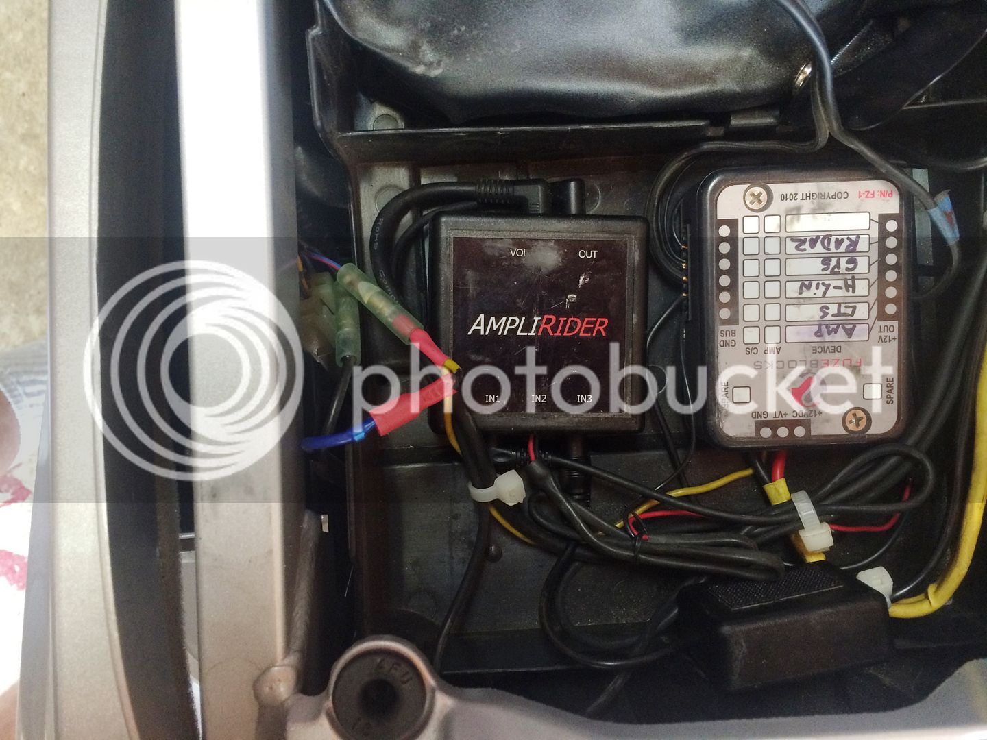
Here's a picture of my setup.

IMG_2696_zps5q7g7ibc.jpg


Is the yellow wire coming from the Fuzeblock that attaches to the blue wire with the red stripe with a bullet connector your trigger wire? On my '16ES this blue wire with the red stripe and a factory bullet connector does not exist. All of the factory wiring under the seat comes from 3 big modular connectors under the "FJR" panel on the left side. One of these 3 connectors only has wiring coming in with no outgoing wires (the 3 outgoing holes are plugged), but to install an outgoing wire would require removing the plug and terminating the wire with a special spade lug that would insert into and mate with the connector. That's assuming that one of these 3 wires (red with white stripe, red with green stripe and gray bands, and black with gray bands) would give me the switched 12V that I need. Sure looks like this connector is meant for connecting future accessories.

These '16ES models with the electronic suspension and LED lighting have tons more wiring and components under the seat.

 
... One of these 3 connectors only has wiring coming in with no outgoing wires (the 3 outgoing holes are plugged), but to install an outgoing wire would require removing the plug and terminating the wire with a special spade lug that would insert into and mate with the connector. That's assuming that one of these 3 wires (red with white stripe, red with green stripe and gray bands, and black with gray bands) would give me the switched 12V that I need. Sure looks like this connector is meant for connecting future accessories....
I think that's the "Yamaha diagnostic tool connector". I'd advise against using any of that. In any case, I don't think any of those wires is switched 12 volts, although the red/green is permanent 12 volts.

 
I tapped into the blue wire in the cable going to the tail section under the passenger seat and I'm getting 12V with just the key turned on without starting the engine--success! As far as I can tell this wire goes to the license plate light and so this LED light must have its driver downstream from where I'm tapping the wire. It might even be built into the light itself--they can be pretty small these days or even embedded in the electronics of the light. A lot of new LED lights are what they call "driverless".

 
Top