USA Gen I Ignition Switch Failure

Yamaha FJR Motorcycle Forum

Help Support Yamaha FJR Motorcycle Forum:

This site may earn a commission from merchant affiliate links, including eBay, Amazon, and others.

adyingbreed

Active member
Joined
Jun 15, 2023
Messages
31
Reaction score
8
Location
California
So, first off, I would like to thank this forum for being where I found the info to get my bike running again.

Secondly, I had an ignition switch failure on a 2004 USA Gen I, via the red wire pulling loose from the switch.

Having good Google-fu brought me to this forum where I found the info on how to diagnose, and temp fix the issue so I am mobile.

My switch had initially only temporarily failed. And unfortunately it was while I was on the freeway. Lost all power while I was in slow lane, as I had just got on the freeway. So luckily I was able to get over to the shoulder and was able to get it going, get off the freeway, and take the canyon road back home (it's all downhill so even if it died I could coast in neutral back to my city).

Cycling the key several times after letting it sit in off position is what got it to work again.

When I finally got it home, I couldn't get the power back on after tuning it off unless I played with the loom going into the bottom of the switch.

It was super tightly zip tied, as others have mentioned. And when I pressed up on a single point (wire) of the loom it would get power again.

So I butchered the loom and twisted the hot wires together. Turns on perfectly. Ugh...

Okay... off to Walmart and harbor freight I go... I have lots of spare butt splices now. The toggle switch I got isn't waterproof, but that just forces me to not make my temp fix permanent.

It works.

I'm going to buy the recall part (saves me hundreds) and replace the whole switch on my own. Just upset that I have to remove the top triple AND drill out security bolts in order to remove the old switch to install new one.
 
My mistake, I thought the Gen I bikes had an ignition switch recall as well as the TPS.
I guess it was just the Gen II.
I still reported it to the Cypress main USA office.

They still have Gen I & II bikes out there with low mileage that can have this safety issue occur.

The rep told me she would most definitely report the issue, but that the recall had been closed years ago, and the recall part is no longer being made.

There are 3 I can find for sale online but they range from 37 to 90 bucks. So I am trying to verify with each vendor if the one they have for sale has the strip of yellow tape.
 
So, first off, I would like to thank this forum for being where I found the info to get my bike running again.

Secondly, I had an ignition switch failure on a 2004 USA Gen I, via the red wire pulling loose from the switch.

Having good Google-fu brought me to this forum where I found the info on how to diagnose, and temp fix the issue so I am mobile.

My switch had initially only temporarily failed. And unfortunately it was while I was on the freeway. Lost all power while I was in slow lane, as I had just got on the freeway. So luckily I was able to get over to the shoulder and was able to get it going, get off the freeway, and take the canyon road back home (it's all downhill so even if it died I could coast in neutral back to my city).

Cycling the key several times after letting it sit in off position is what got it to work again.

When I finally got it home, I couldn't get the power back on after tuning it off unless I played with the loom going into the bottom of the switch.

It was super tightly zip tied, as others have mentioned. And when I pressed up on a single point (wire) of the loom it would get power again.

So I butchered the loom and twisted the hot wires together. Turns on perfectly. Ugh...

Okay... off to Walmart and harbor freight I go... I have lots of spare butt splices now. The toggle switch I got isn't waterproof, but that just forces me to not make my temp fix permanent.

It works.

I'm going to buy the recall part (saves me hundreds) and replace the whole switch on my own. Just upset that I have to remove the top triple AND drill out security bolts in order to remove the old switch to install new one.
Repair yours. Once you get the switch out, take it apart and redo the solder points. All you'll have to do is carefully reheat the solder points. Yes, those factory tamper proof fasteners are a royal pain. Why did they go to all that trouble? I had the same problem. Twice. Since I had already taken the switch apart and put it back together with metric fasteners, the second time was a snap. I should have redone ALL the solder points the first time instead of just the one that came loose. I took a bunch of photos. If I can find where I saved them I will post them, or send to you if are interested.
 
Repair yours. Once you get the switch out, take it apart and redo the solder points. All you'll have to do is carefully reheat the solder points. Yes, those factory tamper proof fasteners are a royal pain. Why did they go to all that trouble? I had the same problem. Twice. Since I had already taken the switch apart and put it back together with metric fasteners, the second time was a snap. I should have redone ALL the solder points the first time instead of just the one that came loose. I took a bunch of photos. If I can find where I saved them I will post them, or send to you if are interested.
Okay, found the photos. There are 4 solder points. Just reheat them enough so they turn from cold joints into a bright shiny solder joint. You can see in the photos how I put the switch back together with metric fasteners. It really is an easy repair, and once you solder it properly you will have the satisfaction of knowing the switch will be good for a long time.
Here's the flickr link:
https://flic.kr/s/aHBqjAHU9G
Thanks I had been looking for internals pictures.

I have never soldered before, also don't have a soldering iron or gun, or even a heat gun. So I may take it to someone for that part once I have it open. But I am also going to have to repair my loom lol. Just used butt splices crimps and electrical tape to attache it to the toggle switch lol.

So either way I am going to be spending more money.
At the very least I do have c clamps to secure it to a bench to drill out security bolts.

Does anyone happen to know size and length of those bolts so I can source the hex head replacements?

Also, what should I torque them to?
 
When my Gen1 ignition switch died, it was burnt contacts. Both times. No amount of soldering will fix that. I retrofitted a Gen 2 switch, swapping out my cylinder so the key remained the same. The Gen 2 switch had heavier duty contacts.
 
When my Gen1 ignition switch died, it was burnt contacts. Both times. No amount of soldering will fix that. I retrofitted a Gen 2 switch, swapping out my cylinder so the key remained the same. The Gen 2 switch had heavier duty contacts.

This is why I want to buy the recall part and just fit my lock barrel to it.
 
Yamaha only uses one side of the key in all their locks/ignition. So you can replace the switch and have a key cut with one side your old key and the other the new switch. Turn the key one way to put it in the ignition and the other for everything else.
 
adyingbreed

The original switch only had one pathway through the switch for the current to travel. Construction for the switch consists of a pair of flat contacts on the circuit board, which is attached to the wires, and spherical contacts on a spring loaded floating copper plate attached to a shaft turned by the key. With a 50 AMP main fuse, this switch will get hot with resistance; so hot that either:
  1. The solder connection will melt sufficiently to allow the wire to pop off the circuit board.
  2. The plastic carrier retaining the spring loaded floating copper plate will deform causing the plate to stick askew as the ignition key is rotated.
If the red wire detaches from the switch, then you are dead on the side of the road. If the plastic carrier is deformed, then multiple attempts at turning off and on with the key may allow it to contact the circuit properly. either way your OEM ignition switch is in a failure mode, and is unreliable.

Your best bet is to obtain a new ignition switch from your Yamaha dealer. This switch was redesigned with two pathways for the current to flow; thereby reducing the amount of resistance/heat in the switch. They will be happy to install it for you – for a price, or you can do it yourself if you are handy with some basic tools. Fitting the tumblers from your OEM ignition switch is quite possible. If you are uncomfortable doing that yourself, then take both ignition switches and keys to a competent locksmith and have them do it. Do what you have to so there is only 1 key for the bike.

Check out this ancient thread – The Recall Ignition Switch - What's new about it? – to see the failure modes with the OEM switch, and how Yamaha fixed the issue with the redesign. You can only buy the redesigned switch from your Yamaha dealer. If you try to get one from e-Bay you have to have a really good look at the pigtail coming from the Ignition switch for that extra white wire, as well as that attached yellow tag.

Good luck with it!

Brodie
🙂
 
Last edited:
Thanks I had been looking for internals pictures.

I have never soldered before, also don't have a soldering iron or gun, or even a heat gun. So I may take it to someone for that part once I have it open. But I am also going to have to repair my loom lol. Just used butt splices crimps and electrical tape to attache it to the toggle switch lol.

So either way I am going to be spending more money.
At the very least I do have c clamps to secure it to a bench to drill out security bolts.

Does anyone happen to know size and length of those bolts so I can source the hex head replacements?

Also, what should I torque them to?
I'm a novice with electrics compared to Brodie so I guess I got lucky. Nothing burnt. Nothing deformed. Just dead one day to the next. First time the red wire solder joint totally came loose. Obvously a cold joint. I cleaned it up with alcohol, fluxed it up, and resoldered to the board. Fixed. Second time one of the other wires came loose, so followed the same procedure. Fixed. No problems since then.
As far as bolt length, I don't recall size or length (5 or 6mm?) but not too difficult to determine. Once you drill out the security bolt heads, take the remnants to your local hardware store for replacements. I recommend getting stainless bolts. Torque? Just tight enough with a little bit o' blue loctite on the threads will be good. Maybe 20 Nm? Sorry I can't be more specific. First repair was probably six years ago, the second over a year ago so details are very fuzzy in my little pea brain.
Good luck with this! Let us know how it turns out.
 
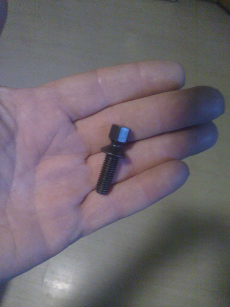
The bolts are M8 x 25. The new switch comes with new security bolts. They are to be tightened until the top hex snaps off the rest of the bolt.
FJR_Ign_sw_bolt.jpg

I still have them because I replaced them with Allen head cap screws.

Rather than drilling them out, I used a Dremel tool to cut a slot in the round top that's left behind and wound them out with a straight bladed screwdriver.

Edit: I should add that the first time the switch failed I was on a trip when it died. My short-term solution to get home was to swap the two blue wires for the red / brown pair. The light gauge blue ones run the computer, the heavier gauge pair feed everything else, but the internal contacts are identical. After cleaning the contacts as best as possible, unsoldering and swapping the wires around got me rolling again and bought time to get a new switch.
 
Last edited:
adyingbreed

The original switch only had one pathway through the switch for the current to travel. Construction for the switch consists of a pair of flat contacts on the circuit board, which is attached to the wires, and spherical contacts on a spring loaded floating copper plate attached to a shaft turned by the key. With a 50 AMP main fuse, this switch will get hot with resistance; so hot that either:
  1. The solder connection will melt sufficiently to allow the wire to pop off the circuit board.
  2. The plastic carrier retaining the spring loaded floating copper plate will deform causing the plate to stick askew as the ignition key is rotated.
If the red wire detaches from the switch, then you are dead on the side of the road. If the plastic carrier is deformed, then multiple attempts at turning off and on with the key may allow it to contact the circuit properly. either way your OEM ignition switch is in a failure mode, and is unreliable.

Your best bet is to obtain a new ignition switch from your Yamaha dealer. This switch was redesigned with two pathways for the current to flow; thereby reducing the amount of resistance/heat in the switch. They will be happy to install it for you – for a price, or you can do it yourself if you are handy with some basic tools. Fitting the tumblers from your OEM ignition switch is quite possible. If you are uncomfortable doing that yourself, then take both ignition switches and keys to a competent locksmith and have them do it. Do what you have to so there is only 1 key for the bike.

Check out this ancient thread – The Recall Ignition Switch - What's new about it? – to see the failure modes with the OEM switch, and how Yamaha fixed the issue with the redesign. You can only buy the redesigned switch from your Yamaha dealer. If you try to get one from e-Bay you have to have a really good look at the pigtail coming from the Ignition switch for that extra white wire, as well as that attached yellow tag.

Good luck with it!

Brodie
🙂
Well shoot. Ignorance is bliss. Now that I've read through the "ancient thread" and understand better how the switch works, maybe my switch is not as good as I had thought. Probably not cold solder joints, but heat related disconnect.
I presume the new switch will retrofit to gen 1?
 
Well shoot. Ignorance is bliss. Now that I've read through the "ancient thread" and understand better how the switch works, maybe my switch is not as good as I had thought. Probably not cold solder joints, but heat related disconnect.
I presume the new switch will retrofit to gen 1?
Disregard that last question. Torch answers it in his post above.
 
Yamaha only uses one side of the key in all their locks/ignition. So you can replace the switch and have a key cut with one side your old key and the other the new switch. Turn the key one way to put it in the ignition and the other for everything else.
Oh snap!

Really?

That would make things slightly easier.

I am still very much incorporating a toggle switch as a hidden kill switch to at least negate the screwdriver and leg theft method, but being able to just cut new keys, and using a punch to mark the side that is oem would make things easier/cheaper.
 
Actually, I do have another question. If I order a gen 1 switch will I get the same ol' switch, or the upgraded switch?
I know the part numbers are different so cross reference those.

I haven't even bought the recall part but know they are different and sold at different prices.
 

Latest posts

Top