RossKean
Well-known member
I want to redo the wiring on my Clearwater lights. They (and and a bunch of other stuff) are hanging off the battery. I want to put everything back to a Fuzeblock FZ-1. This stuff was set up by the previous owner and if it was working 100%, I would just leave it alone. I am having a couple of issues and thought I would use the opportunity to simplify the overall wiring scheme.
There is a set of Ericas and a set of Glendas and both sets of lights are powered by a single Clearwater "relay box". The Ericas draw 5 amps each and the Glendas draw 1 amp each for a total of 12 amperes. Although the FZ-1 is rated for a total of 30 amps, each individual circuit is only rated for 10 amps. Clearly, the combined draw of the two set of lights would exceed this leading to blown fuses or the escape of the magic smoke.
Since the Clearwater relay box only has a single power inlet, it would seem that the FZ-1 would not be suitable for this application. I was wondering if it would be acceptable to split the line powering the relay box and feed it from two circuits on the FZ-1? Would the power draw from each of the two circuits be sufficiently balanced to ensure it wasn't overloaded? I suppose if the draw was sufficiently lopsided for some reason, the high current side would pop its fuse followed immediately by the other side assuming that each side was fused at no more than 10 amps (perhaps even 8 amps). (This is beginning to sound like a bad idea.)
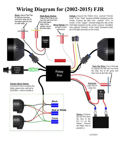
This is the Clearwater schematic:

The other (probably better) option is to set up a simple barrier strip in the front of the bike and run that a short distance to the battery. I could run the Clearwater relay off this as well as the FZ-1, voltmeter display and battery tender/Slime pump outlet as well. I would use the FZ-1 (switched side) for Zumo, heated gear, trailer lighting harness and anything else I wanted to hook up. This still maintains my primary objective of minimizing the number of wires going back to the battery. Once set up for the lights, voltmeter and FZ-1 (and maybe SAE plug), there would be no need to have ready access to the barrier strip. Any "switched" circuits and any new add-ons or changes would go to the Fuzeblock.
For anyone who has used a barrier strip for power distribution, any suggestions on location for a Gen II? I think I would like to keep it near the front of the bike to minimize the length of high current wire runs and have the FZ-1 under the seat. It would get its trigger signal from the taillight. (Keeps the higher current stuff out of the hot engine compartment as well)
Any simple barrier strips out there with covers to help keep out the elements and errant opportunities to short circuit stuff? I would probably fuse the barrier strip at 40 amps which is more than will ever be running on this bike. One channel for input and three or four for output. Any downside in doing it this way?
There is a set of Ericas and a set of Glendas and both sets of lights are powered by a single Clearwater "relay box". The Ericas draw 5 amps each and the Glendas draw 1 amp each for a total of 12 amperes. Although the FZ-1 is rated for a total of 30 amps, each individual circuit is only rated for 10 amps. Clearly, the combined draw of the two set of lights would exceed this leading to blown fuses or the escape of the magic smoke.
Since the Clearwater relay box only has a single power inlet, it would seem that the FZ-1 would not be suitable for this application. I was wondering if it would be acceptable to split the line powering the relay box and feed it from two circuits on the FZ-1? Would the power draw from each of the two circuits be sufficiently balanced to ensure it wasn't overloaded? I suppose if the draw was sufficiently lopsided for some reason, the high current side would pop its fuse followed immediately by the other side assuming that each side was fused at no more than 10 amps (perhaps even 8 amps). (This is beginning to sound like a bad idea.)
This is the Clearwater schematic:

The other (probably better) option is to set up a simple barrier strip in the front of the bike and run that a short distance to the battery. I could run the Clearwater relay off this as well as the FZ-1, voltmeter display and battery tender/Slime pump outlet as well. I would use the FZ-1 (switched side) for Zumo, heated gear, trailer lighting harness and anything else I wanted to hook up. This still maintains my primary objective of minimizing the number of wires going back to the battery. Once set up for the lights, voltmeter and FZ-1 (and maybe SAE plug), there would be no need to have ready access to the barrier strip. Any "switched" circuits and any new add-ons or changes would go to the Fuzeblock.
For anyone who has used a barrier strip for power distribution, any suggestions on location for a Gen II? I think I would like to keep it near the front of the bike to minimize the length of high current wire runs and have the FZ-1 under the seat. It would get its trigger signal from the taillight. (Keeps the higher current stuff out of the hot engine compartment as well)
Any simple barrier strips out there with covers to help keep out the elements and errant opportunities to short circuit stuff? I would probably fuse the barrier strip at 40 amps which is more than will ever be running on this bike. One channel for input and three or four for output. Any downside in doing it this way?
Last edited by a moderator:


