RESISTORS (no, it's NOT a soccer team....)

Yamaha FJR Motorcycle Forum

Help Support Yamaha FJR Motorcycle Forum:

This site may earn a commission from merchant affiliate links, including eBay, Amazon, and others.

kaitsdad

I'm confused - Just ask my Wife.
FJR Supporter
Joined
Oct 16, 2005
Messages
2,956
Reaction score
63
Location
Orange, CA
I need to understand the functioning/limitations of a resistor - this is due to the information I've uncovered with the help of the forum members that posted in my Audiovox CCS100 Poll recently.

I've done oodles of internet research, but I've still got the blender spinning with all the information I've poured through. So - I have some questions - and I'm hoping that one of the many electrical gurus on this forum will help us out here -

OK - The audiovox CCS 100 has a lead that per the instructions, is supposed to tie into one of the coil wires, it's purpose is to sense engine speed. This lead has a resistor wired in series.

This resistor measures 20K Ohm, and it's purpose, as I understand it, is to filter out (essentially 'smooth' out) the firing pulses coming from the coil.

(EDIT March 7 to correct resistor value - Thanks, guys !)

The resistor used by Audiovox looks like this:
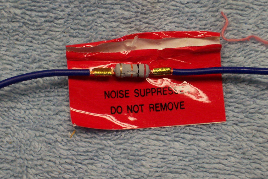
262516946_qPHuT-XL.jpg


This resistor shows a gold band, which indicates that the tolerance is +/-5% - however, I understand that the value can change with temperature - but to what degree I don't understand.

So - there are two questions I have -

1. Does anyone understand or know the degree to which the resistance changes with temperature INCREASE in a ceramic resistor? (Okay, there's a subset question next:)

1.a And what way does the resistance change - does the resistance INCREASE or DECREASE with the temperature increase?

And now for the second question:

2. This is a good one: We are all aware that the GenII bikes have a larger wattage output from the stator - could this possibly result in a higher wattage hitting the coil wires than on a GenI bike? I.E., more "noise" on the wire?

OK - I just thought of a third - (fourth?) How does one go about measuring resistance of a resistor?

Thanks in advance for your answers. I appreciate it.

Just for everyones' information -

There seems to be two different symptoms of the problems -

the first being: Failure to hold a speed -

the second being: Failure to engage.

These symptoms are being investigated concurrently by two different people - so everyone just be patient, and we'll continue to cook along on these.

Having fun yet ?

 
Last edited by a moderator:
The purpose of a resistor is to reduce the voltage of a power supply. (Power supply being a battery or other source.) Ohm's law applies to all things electronic.

Resistance INCREASES with temperature. The degree of change in a 5% resistor is relatively small, but varies from manufacturer to manufacturer. It doesn't change enough at FJR temperatures to worry about.

Alternator output is not relevent to the purpose of the resistor.

One measures resistance with an Ohm meter. It can be indirectly measured by testing the voltage difference between one side of the resistor (in circuit) and the other side of the resistor (in circuit).

HOWEVER, this particular resistor, in this particular application would be virtually impossible to measure without an oscilloscope, a bit of training, and a calculator so you can do the math from Ohm's Law.

Let me explain what this resistor does.

When a spark coil is powered, electricity passes thru a large 'spool' of wire. As the electricity is passed thru the coil, a powerful magnetic field is created. When the electricity is stopped/removed, the entire magnetic field collapses around itself and a huge spark is created as the voltage multiplies thousands of times as the natural effect of the collapsed field.

Thus, a spark can be made to jump across a sparkplug.

HOWEVER, a side effect of this phenomenon is that the voltage at the input (12 volt) side of the coil is also multiplied by the collapse. Voltages at the positive lead are often in the range of 200 volts DC.

If you look at the actual signal (voltage v time) on an oscilloscope, you'll find that the signal may contain one or two extreme spikes in the 200 volt range, but the rest of the signal will be at 'manageable' levels.

The purpose of the resistor is to prevent the extremely brief 200 volt spikes from turning into radio signals and/or prevent them from arcing across circuit board traces.

Since Ohm's law is a mathematical function, the resistor will 'resist' the 200 volt spikes much more than it does the 12 volt supply. Thus, it's effect on the function of 'engine speed sensor' is extremely minimal.

 
Last edited by a moderator:
Thanks Andre, that was as good an explanation about resistors and spark firing as I've heard, read.

Now that it looks like resistor issues might be elimitated from all the CCS problems that 2nd gen owners have had (not me, though, thankfully), I wonder why the heck there are installation failures, and why are they sporadic. Hmmmmmmm... :dntknw:

 
Nice picture! I see the resistor has a small surgical scar :lol: The stripes on the resistor say that it is a 20k ohm reisistor and you have correctly identified it as a 5% part. In electronics 0 = black (stripe); 1 = brown (stripe); 2 = red (stripe); 3 = orange, 4 = yellow and so on. Your resistor is red, black, orange so it is the number two, followed by the number zero followed by three zeros = 20K. A silver band denotes a 10% part; gold is a 5% part and a brown stripe is a 1% part (brown = 1). Most common resistors go up in value when they get hot, usually the manufacturer specs the resistors to change something like 1,000 parts per million per °C of temperature change. In English, that means that the resistor value does not change very much even when it gets very hot. Most resistors are 'positive coefficient' parts, meaning they go up in value when hot. You can buy 'negative coefficient' resistors that go down in value when they get hot but you have to really look for these.

The AVCC is a universal cruise intended for automotive applications, though it can be adapted to almost any conventional drive system. The AVCC may be attached to either a mechanically timed vehicle -- points, or electronically timed -- electronic ignition like all cars have these days. The point ignition systems are prone to many more electrical disturbances on the 12 volt line than an electronic system.

The 20k resistor will reduce current going into the AVCC to 600 micro amps at 12 volts; that is .0006 amps. Even if it sees 200 volts as Andre mentions that is still only 10 milliamps; .010 amps. All very small units.

Edited to add: The resistor reduces the current of the coil wire signal going to the AVCC, making it easier for the AVCC to internally filter the signal.

Surprisingly, the AVCC control circuit has a very small number of active components. There is significant +12 volt filtering to stabilize main 12 volt power for the AVCC. All the smarts for the cruise are contained in just one custom made IC fabricated by FreeScale someplace in the Far East. There are three transistors that switch the three vacuum solenoids and that is essentially it. Every signal that goes into the AVCC's 10 wire connector first go through diodes, resistors and capacitors to clamp and massively filter the signals, then they go straight to the CPU.

Several FJRs with the common failure symptoms have had the control signal changed from the coil wire to a magnetic pick-up which uses different pins and filtering to the AVCC CPU so I'm not at all that convinced that the problem is the coil signal.

I still need to get hold of Smitty and have a chat with him and see what he has already done. Hal, I have a half written letter to you, I will get it done and in the 'mail' soon ;) :)

 
Last edited by a moderator:
As a follow-up question...

With a system using a Back-Off module, what resistor should I install?

My current system has the stock tail lights. I have teed into the stop light wiring to power the Back-Off module which in in line to a 6" LED accesory strip.

 
As a follow-up question...

With a system using a Back-Off module, what resistor should I install?

My current system has the stock tail lights. I have teed into the stop light wiring to power the Back-Off module which in in line to a 6" LED accesory strip.

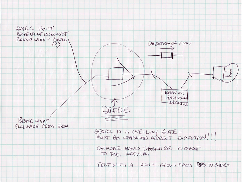
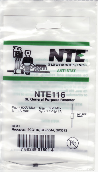
Luke, a backoff module needs a DIODE - not a resistor. Hope this helps.

(Please excuse the crayon-like drawing)

191692778_8zzTi-L.jpg


191692856_rPKpQ-L.jpg


You can use any readily available Radio Shack diode numbered from 1N4001 to 1N4004 for the Back Off circuit.

 
Several FJRs with the common failure symptoms have had the control signal changed from the coil wire to a magnetic pick-up which uses different pins and filtering to the AVCC CPU so I'm not at all that convinced that the problem is the coil signal.
I was under the impression from following the CC threads that the magnetic pickups were tried because the coil wire pickup didn't work. Usually the magnetics didn't work any better.

Strangely enough, the Gen-II problem discussed here is the same thing that happened to me installing the CC on a Miata that belonged to my son. Would set for a few seconds using the coil pickup, would set for several minutes using the magnetic pickup, but never worked correctly, could not convince Autozone or Audiovox that it was defective. Pulled it and threw it away, swearing never to go back.

Obviously, I went back, and the unit on my '03 Feej has been flawless.
You're correct, Smitty tried a magnetic pickup to see if it worked any better - and it didn't. He told me he spent 25 hours on one unit trying to get it to work and was not successful. He then refunded the buyer's money.

I wish you still had that bad unit - that's one of the problems - the incompatable units that Smitty had were reinstalled, so they're not available for torturing testing.

 
Last edited by a moderator:
It is alleged that Smitty took 4 AVCC units that were failing in Gen IIs and put them in Gen Is and they work just fine. This would indicate that the AVCCs are not entirely bad but may be susceptible to some kind of electrical irregularity that is unique to some of the Gen IIs.

Edit: I need to start typing faster! Hal had it covered.

 
Last edited by a moderator:
It is alleged that Smitty took 4 AVCC units that were failing in Gen IIs and put them in Gen Is and they work just fine. This would indicate that the AVCCs are not entirely bad but may be susceptible to some kind of electrical irregularity that is unique to some of the Gen IIs.

Bingo. Smitty's failed installs were all "Failure to engage".

Or that those particular units had a component that was marginal, and that combined with the GenII irregularity in those particular bikes resulted in a fail.

I guess that's what you said, isn't it. :blink:
My impression after talking with Smitty in the past and reading other's posts was that the problem was not failure to engage but instead failure to stay engaged. They would initially engage and then fail with the period of engagement decreasing with time. Mine will almost always engage initially and then get flaky with time. Initially they work great but as the ride progress the time of engagement decreases (edit: changed from increases to decreases) to the point of uselessness. Am I right in this clarification?

 
Last edited by a moderator:
My impression after talking with Smitty in the past and reading other's posts was that the problem was not failure to engage but instead failure to stay engaged. They would initially engage and then fail with the period of engagement decreasing with time. Mine will almost always engage initially and then get flaky with time. Initially they work great but as the ride progress the time of engagement increases to the point of uselessness. Am I right in this clarification?
Yes, that is correct. Smitty said the units would work from 5 to 15 minutes or so, and then shut off and not re-engage. Smitty is in the middle of a 50/50 ride on his CCS controlled KTM, so he won't chime in here, until he gets to Florida for that IBA pizza thing. He did take his laptop, though. Oh, and yes, I think he's re-used all the failed units. He's way too cheap to toss them, so I'm fairly certain he's used them on gen 1 bikes.

I'm baffled as to why my unit works. Installed a couple on '04s (and a Miata, and a Galant, all worked flawlessly), and then installed a unit on my AE hooking it up the same way. 10K miles and no hickups. Wish someone could get to the bottom of the problem. Sounds like ION and Hal are trying pretty hard. Thanks guys.

I almost feel guilty that mine works.... and it sits within an inch of my header pipes in the chin. :thumbsup:

 
Last edited by a moderator:
Just got off the phone with Smitty. He's about 40 miles outside Houston on his way to Jacksonville. KTM is running well, sounds like the pilot is holding up pretty well, too.

Smitty confirmed that he's not had any units that he couldn't get working on a different bike. Sometimes the same unit would not work on one Gen II and then he'd swap it to a different Gen II, and then it would work. It's so crazy and he's wasted so much time trying to get Gen IIs to work, he's given up installing them on Gen II bikes.

Anyway, he and I discussed the possibility of changing out the resistor to a different size and see if that had any effect. Based on what was explained above, sounds like we were barking up the wrong tree on that one. Glad some of you guys know what's happening. Standing by eagerly to see if anyone finds a definitive solution.

 
The resistor they install is a "best guess" for universal application. There should also be other tach signals in the wiring harness somewhere. Anyone with a Service manual for Gen II's want to dig?

I can get scope plots of the Gen 1 bike, and if someone in the area has a Gen 2 they can bring by, I could get a plot of it as well.

Swapping this resistor value may or may not help the cpu latch on to the tach signal. *If* the unit loses the tach signal, it will disengage, so it *could* be a cause of the problem. Purely speculation.

If you were to go about changing this resistor to help the problem, I would start with comparing the scope plots of the Gen 1 and Gen 2 bikes, and look for any obvious differences, then gradually compensate. If there were not any obvious differences in the signal, it would be much harder to identify as a source of the problem.

You could also measure the resistors on several units with and without the problem. The hard part would be to slowly watch the rise or fall of the resistance with temperature (soldering iron underneath). It could be as simple as a bad batch of resistors that whack out at XXX degrees. You would have to compare the results from several, both working and non working to make any sense of it.

I have no dog in this fight though, my Gen 1's CC works fine, has since day 1.

 
Last edited by a moderator:
If the resistor was the issue why don't all of the of the Gen II's suffer from this problem? I would start collecting data on VIN's and look for differences in the model years.

 
I've installed three Audiovox cruise controls with no problems.

I know from personal experience that the purple wire must be grounded for the cruise to work. Could the problem be an intermittent or loss of ground on the purple wire?

Has anyone used a relay on the brake light circuit for the ground connection on GenII bikes with non-working cruise? Did it fix the problem?

 
Top