droptail
Well-known member
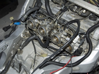
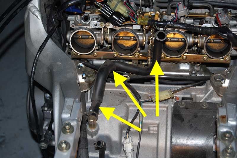
There is a harness that originates from the lower back of the engine and goes up and forward disappearing under the air box.
I want to know where the harness routes to.
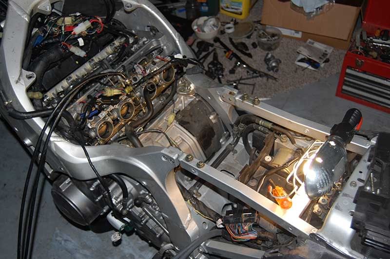
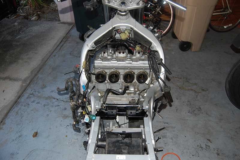
Is there a picture of the top of the engine with the tank off also?
Thanks
I want to know where the harness routes to.
Is there a picture of the top of the engine with the tank off also?
Thanks