JimLor
Well-known member
I wanted to pass on my experience and my story on my ESG 130 install and then re-install. So, here goes!
For those who are not mechanically inclined, the stator resides here, just under the crankcase cover with “Yamaha” on the outside.

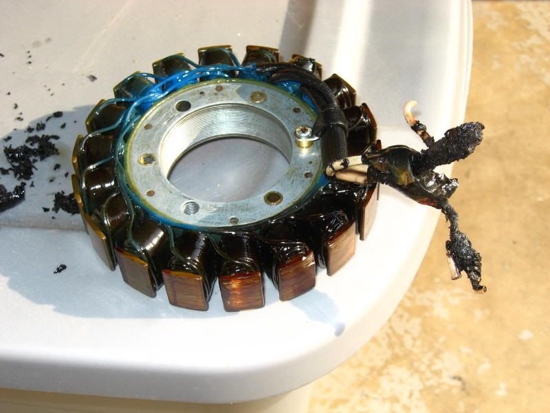
Here’s a picture of the “new” ESG stator:
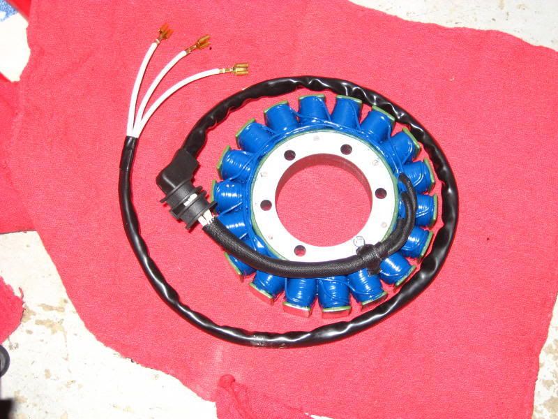
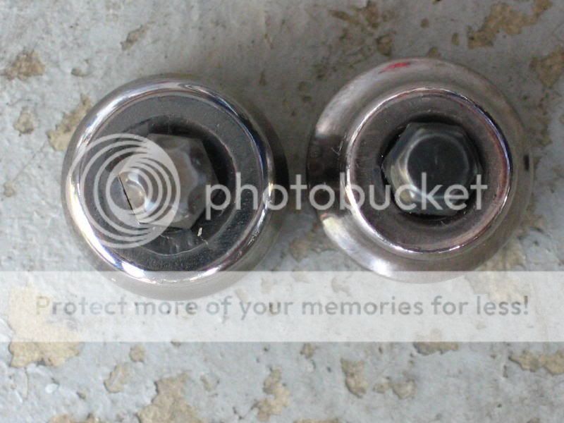
Something you have to consider up front is whether you want to retain the OEM connection into the Regulator / Rectifier (RR), or use the connections that come on the ESG. The OEM stator connector is actually the gray one behind the more visible black one, but they are basically the same.
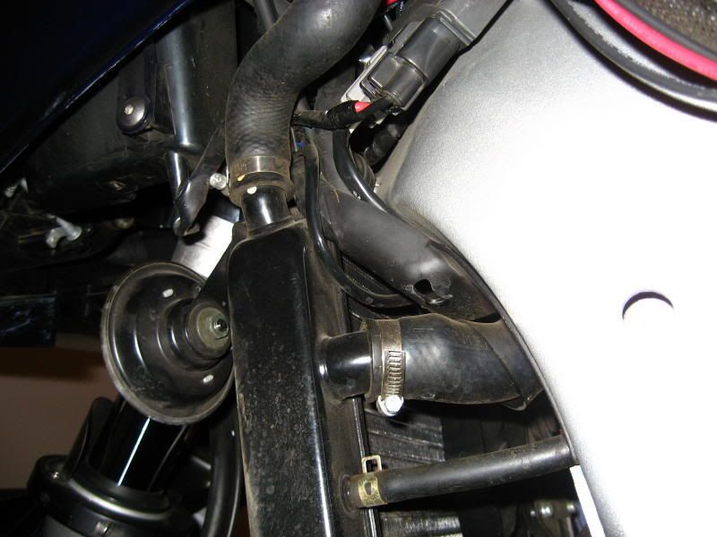
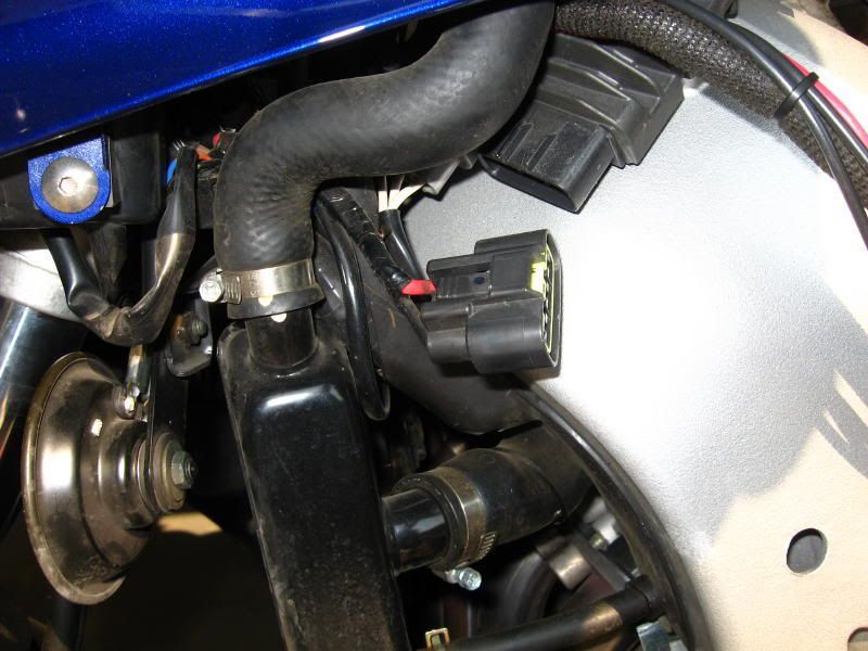
As you can tell, the OEM connector is pretty substantial and no doubt water resistant. From the picture of the stator you can see that the ESG just uses open female spade connectors. Not a tough decision for me to make. I chose to retain the OEM connector and cut/splice the ESG wiring into the existing wiring. Next step is to decide where to do the splice. (I chose the splice location poorly on my first stator – I did it inside the crankcase cover – poor, very poor, choice. I’ll discuss that later!) In order to get some weather protection for the splice, I chose to do it under the rubber thingy next to the tank. Here’s a picture:
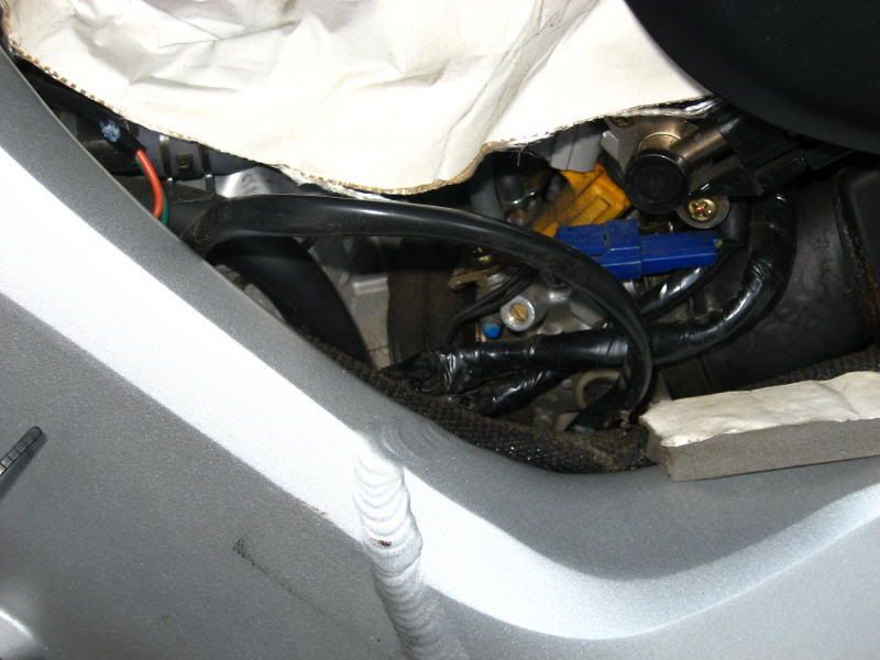
The stator wiring runs thru here on its way to the RR; easy to get to and does provide some additional weather protection.
So, choice made, here’s how to proceed:
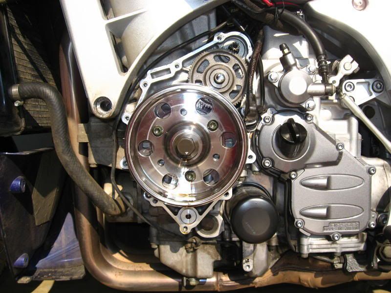
Remove the left side fairing. Raise the tank and remove the rubber thingy. Remove the crankcase cover (standard allen wrench) – oil does flow thru this area when the engine is running, but most of it drains away when you shut down. Put an oil pan under the cover, you’ll get about an ounce or so coming out when you remove the cover. What happens in here is that the crankshaft spins (has magnets around it) in the center of the stator which induces a current which travels to the RR where magic turns A/C to D/C and maintains a steady voltage output. So, when you remove the cover you will feel fairly significant resistance – that the magnets. Gird your loins and pull the cover off. Here’s what you’ll see with the cover removed:
There are 2 x “dowels” that fit close by 2 of the bolts and they may come out with the cover. No problem, just stick ‘em back in when you’re ready. They let you hang the gasket and help center the cover when you put it back on. Here’s a picture of the gasket:
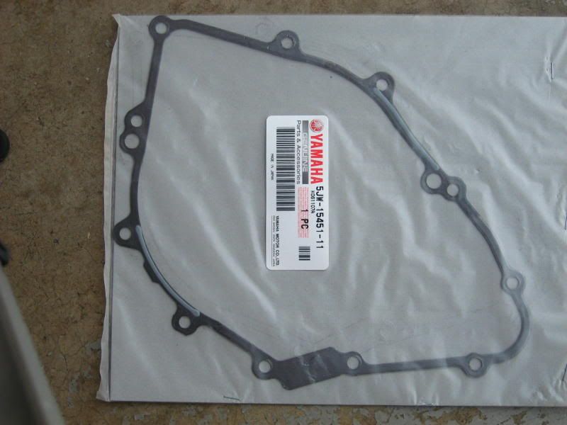
…the dowels fit in the “extra” holes at 7 and 3 o’clock. You may also pull out the large gear at the top of the picture when you remove the cover, I did the second time I removed it. The shaft can also come out, just reposition the gears and stick the shaft back in – do make sure it fits correctly, but it’s no big challenge.
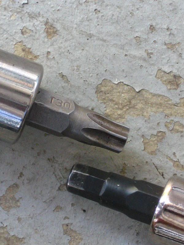
Remove the stator. There are 3 x T30 Torx screws – if you haven’t seen a Torx socket, here it is on the left with a regular Allen on the right:
Then remove the wire holder assembly. 1 x screw that is supposed to be torqued to around 5 lbft, but I had to use an impact wrench to remove!
Prior to re-installing the stator, you will need to remove the gasket/gasket material from the case and from the bike side. I used Gasket remover and a plastic putty knife.
Now, put the new stator in. Torque for the 3 x Torx screw is 7.2 lbft. Arrange the wires and insert the wire holder – torque is 4.3 lbft. Now, you need to use hi-temp silicone sealant (Red) around the rubber grommet thru which the wires run. That is supposed to “cure” for 24 hours – and in fact I did let it cure. At this point you can put on the new gasket and the crankcase cover. And remember, there are magnets at work here so you do need to be “firm.” Cover bolts are 8.7 lbft of torque. Note, I stripped one bolt (1st bolt from bottom center headed counter-clockwise – I had the wrench set to 9 lbft. I’m going to buy a torque wrench capable of finer (smaller) accurate settings. FYI, no leakage from that part of the cover in about 1k miles. Will probably exercise the helicoil option at some point.
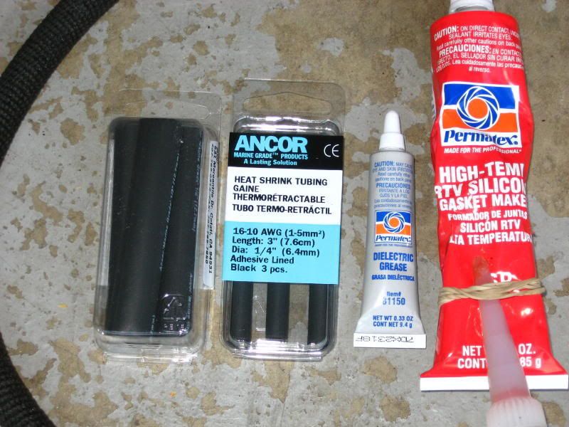
At this point you need to cut and splice (if that’s your choice). I ran the ESG wires up to the cut/splice point. Then, cut and splice! To make the best connection I possibly could, I soldered, covered with Dielectric grease, used nautical heat shrink, then another nautical heat shrink over all 3 wires, and then electrical tape over the ends! Here’s a picture of the stuff I used (left to right is the ….
At this point, lower the tank and secure, put the left fairing back on, and wait 24 hours for the silicone sealant to cure. To be honest, I did start ole’ Maxine just to check the voltage – it was good to go! I didn’t let it run enough to heat up the crankcase cover and the silicone sealant.
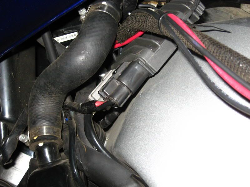
If you chose to use the ESG connectors into the RR, you’ll need to get to the gray stator plug into the RR. If you are very patient, you might be able to remove the OEM and plug the 3 x female space connectors in without removing any more plastic, but I kinda doubt it. If you chose, you might try to remove the radiator hose and sneak behind it…..or, remove the left side cowling, and the black (05 year) panels on the left side. I gotta tell you, in my opinion removing the left cowling is a pain in the *** and I would personally do almost anything not to remove it – again!
This is one of those tasks that may seem daunting at first, but when you break it down into its component parts, it really isn’t a difficult job. Yes, if you screw up, well, you’re screwed!! But, not a bad job overall and another opportunity to learn and experience something new.
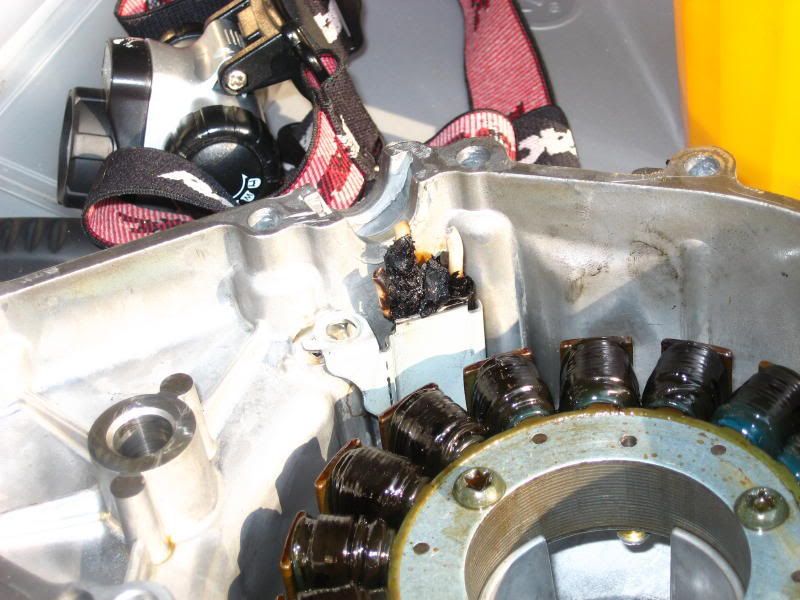
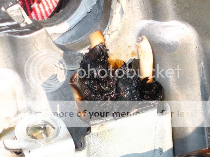
For my original ESG install and the “mistake.” I chose to use the OEM connector. My mistake was that I chose to cut/splice inside the crankcase cover! Big mistake, do not, do not repeat my mistake! I didn’t have room to solder, etc so ended up using crimp connectors and electrical tape. I absolutely knew that at some point this would fail. And by golly, I was right! Here are a couple of pictures of the results of a “poor” connection:
Because I knew this would fail at some point, I installed a Datel Voltmeter on my right side panel – over the battery. Interesting readings. When working correctly (stator that is), my Datel reads 14.1 or 14.2v on startup. Once warmed up, and especially in warmer weather, that will drop to 13.9 or 14.0v. Turning my heated grips to high drops that by 0.2v (lo is 0.1). Turning on my Hella FF-50s drops that by 0.6v. GPS / bike to bike radio / Autocom intercom don’t register any drop. Widder heated vest will drop it anywhere from 0.1 to, if I recall correctly, 0.6v depending on setting (0-7). And the vest will also cause the Datel to fluctuate as the vest cycles.
I was able to tell when my connection finally failed. I started off to work one day and the Datel read 12.9 – 13.2v and fluctuated. I said what the heck and headed out. At highway speeds (~3 -4 k RPM) the Datel read 14.0v. At idle, it read 12.8 to 13.2v. So, I figured my connections were headed to failure. I actually rode the bike for a couple of days. Then 2 Saturdays ago I took Lorie for a couple hour ride. Got home, picked up some papers I had to take to a buddies house…..once moving I noticed the Datel reading 11.9 – oh crapolino! So I quickly turned around and rode the roughly 2 miles home. By the time I got home it was reading about 11.2v. Now I have never seen a concrete answer as to what point (reading) you are no longer charging the battery, but are in fact discharging the battery because the generator/alternator is not longer working. I feel real safe in saying that 11.9v is past that point. I figured a reading of at least 12.5v meant I was at worst keeping even. Anyway, new stator arrived 2 days later and here we are. Rode roughly 1k miles to, around, and back from EOM with no problems.
If anyone has any questions I’d be happy to answer them – as long as you understand the guy providing you answers has done this exactly 2 times, 1 time the wrong way and 1 time the right way (or it would seem so!).
For those who are not mechanically inclined, the stator resides here, just under the crankcase cover with “Yamaha” on the outside.
Here’s a picture of the “new” ESG stator:
Something you have to consider up front is whether you want to retain the OEM connection into the Regulator / Rectifier (RR), or use the connections that come on the ESG. The OEM stator connector is actually the gray one behind the more visible black one, but they are basically the same.
As you can tell, the OEM connector is pretty substantial and no doubt water resistant. From the picture of the stator you can see that the ESG just uses open female spade connectors. Not a tough decision for me to make. I chose to retain the OEM connector and cut/splice the ESG wiring into the existing wiring. Next step is to decide where to do the splice. (I chose the splice location poorly on my first stator – I did it inside the crankcase cover – poor, very poor, choice. I’ll discuss that later!) In order to get some weather protection for the splice, I chose to do it under the rubber thingy next to the tank. Here’s a picture:
The stator wiring runs thru here on its way to the RR; easy to get to and does provide some additional weather protection.
So, choice made, here’s how to proceed:
Remove the left side fairing. Raise the tank and remove the rubber thingy. Remove the crankcase cover (standard allen wrench) – oil does flow thru this area when the engine is running, but most of it drains away when you shut down. Put an oil pan under the cover, you’ll get about an ounce or so coming out when you remove the cover. What happens in here is that the crankshaft spins (has magnets around it) in the center of the stator which induces a current which travels to the RR where magic turns A/C to D/C and maintains a steady voltage output. So, when you remove the cover you will feel fairly significant resistance – that the magnets. Gird your loins and pull the cover off. Here’s what you’ll see with the cover removed:
There are 2 x “dowels” that fit close by 2 of the bolts and they may come out with the cover. No problem, just stick ‘em back in when you’re ready. They let you hang the gasket and help center the cover when you put it back on. Here’s a picture of the gasket:
…the dowels fit in the “extra” holes at 7 and 3 o’clock. You may also pull out the large gear at the top of the picture when you remove the cover, I did the second time I removed it. The shaft can also come out, just reposition the gears and stick the shaft back in – do make sure it fits correctly, but it’s no big challenge.
Remove the stator. There are 3 x T30 Torx screws – if you haven’t seen a Torx socket, here it is on the left with a regular Allen on the right:
Then remove the wire holder assembly. 1 x screw that is supposed to be torqued to around 5 lbft, but I had to use an impact wrench to remove!
Prior to re-installing the stator, you will need to remove the gasket/gasket material from the case and from the bike side. I used Gasket remover and a plastic putty knife.
Now, put the new stator in. Torque for the 3 x Torx screw is 7.2 lbft. Arrange the wires and insert the wire holder – torque is 4.3 lbft. Now, you need to use hi-temp silicone sealant (Red) around the rubber grommet thru which the wires run. That is supposed to “cure” for 24 hours – and in fact I did let it cure. At this point you can put on the new gasket and the crankcase cover. And remember, there are magnets at work here so you do need to be “firm.” Cover bolts are 8.7 lbft of torque. Note, I stripped one bolt (1st bolt from bottom center headed counter-clockwise – I had the wrench set to 9 lbft. I’m going to buy a torque wrench capable of finer (smaller) accurate settings. FYI, no leakage from that part of the cover in about 1k miles. Will probably exercise the helicoil option at some point.
At this point you need to cut and splice (if that’s your choice). I ran the ESG wires up to the cut/splice point. Then, cut and splice! To make the best connection I possibly could, I soldered, covered with Dielectric grease, used nautical heat shrink, then another nautical heat shrink over all 3 wires, and then electrical tape over the ends! Here’s a picture of the stuff I used (left to right is the ….
At this point, lower the tank and secure, put the left fairing back on, and wait 24 hours for the silicone sealant to cure. To be honest, I did start ole’ Maxine just to check the voltage – it was good to go! I didn’t let it run enough to heat up the crankcase cover and the silicone sealant.
If you chose to use the ESG connectors into the RR, you’ll need to get to the gray stator plug into the RR. If you are very patient, you might be able to remove the OEM and plug the 3 x female space connectors in without removing any more plastic, but I kinda doubt it. If you chose, you might try to remove the radiator hose and sneak behind it…..or, remove the left side cowling, and the black (05 year) panels on the left side. I gotta tell you, in my opinion removing the left cowling is a pain in the *** and I would personally do almost anything not to remove it – again!
This is one of those tasks that may seem daunting at first, but when you break it down into its component parts, it really isn’t a difficult job. Yes, if you screw up, well, you’re screwed!! But, not a bad job overall and another opportunity to learn and experience something new.
For my original ESG install and the “mistake.” I chose to use the OEM connector. My mistake was that I chose to cut/splice inside the crankcase cover! Big mistake, do not, do not repeat my mistake! I didn’t have room to solder, etc so ended up using crimp connectors and electrical tape. I absolutely knew that at some point this would fail. And by golly, I was right! Here are a couple of pictures of the results of a “poor” connection:
Because I knew this would fail at some point, I installed a Datel Voltmeter on my right side panel – over the battery. Interesting readings. When working correctly (stator that is), my Datel reads 14.1 or 14.2v on startup. Once warmed up, and especially in warmer weather, that will drop to 13.9 or 14.0v. Turning my heated grips to high drops that by 0.2v (lo is 0.1). Turning on my Hella FF-50s drops that by 0.6v. GPS / bike to bike radio / Autocom intercom don’t register any drop. Widder heated vest will drop it anywhere from 0.1 to, if I recall correctly, 0.6v depending on setting (0-7). And the vest will also cause the Datel to fluctuate as the vest cycles.
I was able to tell when my connection finally failed. I started off to work one day and the Datel read 12.9 – 13.2v and fluctuated. I said what the heck and headed out. At highway speeds (~3 -4 k RPM) the Datel read 14.0v. At idle, it read 12.8 to 13.2v. So, I figured my connections were headed to failure. I actually rode the bike for a couple of days. Then 2 Saturdays ago I took Lorie for a couple hour ride. Got home, picked up some papers I had to take to a buddies house…..once moving I noticed the Datel reading 11.9 – oh crapolino! So I quickly turned around and rode the roughly 2 miles home. By the time I got home it was reading about 11.2v. Now I have never seen a concrete answer as to what point (reading) you are no longer charging the battery, but are in fact discharging the battery because the generator/alternator is not longer working. I feel real safe in saying that 11.9v is past that point. I figured a reading of at least 12.5v meant I was at worst keeping even. Anyway, new stator arrived 2 days later and here we are. Rode roughly 1k miles to, around, and back from EOM with no problems.
If anyone has any questions I’d be happy to answer them – as long as you understand the guy providing you answers has done this exactly 2 times, 1 time the wrong way and 1 time the right way (or it would seem so!).
Last edited by a moderator: