Hyper-Lite Question

Yamaha FJR Motorcycle Forum

Help Support Yamaha FJR Motorcycle Forum:

This site may earn a commission from merchant affiliate links, including eBay, Amazon, and others.

Leghorn

Well-known member
Joined
Jan 9, 2006
Messages
92
Reaction score
1
Location
Arlington, VA
First-Timer (Long-Time Lurker)

I'm adding Hyper-Lites and I would like to avoid cutting into the existing wiring if possible, per www.bikes-n-spikes.org. under "Mods." As will be obvious from my questions, I'm electrically challenged, so apologies to all.

Bounce indicates that he "extracted the pins in the connector on the bike side, attached the Hyper-Lite wires, and then reseated the pins." What is meant by "on the bike side"? (bike v. battery or bike v. light) Put another way, is the extraction made from the male half of the connector? Also, I assume that you extract the pins with needle-nose pliers and then solder the additional wire to the extracted pin for the best connection. Any tips or assistance would be greatly appreciated.

Thanks.

 
Okay, I figured out how to extract the pins from the connector -- there's a clip for each pin that locks the pin inside the connector -- it has to be depressed to make the extraction. I'm working on the male end of the connector so that I can retain the option of removing the tail light assembly even with the Hyper-Lites in place. Also, based on voltmeter readings, I've concluded that the yellow wire is the brake light and that black is ground. (Hopefully, that's correct.)

Bounce, what type of splice did you use to connect the Hyper-Lite hot and ground wires to the existing wiring? The pin is a pretty tight fit within the connector as it is and it seems that a solder joint would make the pin and wiring to bulky to reinsert into the connector. I've considered a splice upstream of the pin but, again, it would be nice not to have to cut into the existing wiring.

 
I used a "pin extractor" (really a jewler's screwdriver) and pulled the required pins from the connector then fed the Hyper-Lite wires back into the connector when re-inserting the pins into the connector. Been working great guns ever since. No splicing or dicing or julianne frying.

"bike side" vs "tail light side". iow: bike-side=the-bike's-main-harness (as you saw, it's the male side of that connector).

https://www.bikes-n-spikes.org/mods/hyper/hyper.html

oem wire->male connector<->female connector<-oem tail lights

h-l wire--->male connector

think of it as both wires (OEM and H-L) Y'ing in from the back of the male connector as shown here:

fjr-hyper02.jpg


The hyper-lite wiring enters the back of the male connector from the right in the photo shown. It's a crimp connection... well... a press fit. As you noticed the fit is tight and it's not much more than a friction fit. But it's held up for nearly 3 years without a hint of problems. I really prefer a crimp+solder connection when doing wiring harness type installations, but the OEM connector is a crimped pin pushed through a plastic connector. This mod is essentially the same quality without actually cutting into any OEM bits.

If, at some time in the future, I have a concern about the reliability of the connection, then I'll clip the wire that goes into the pin with enough length remaining so that I can use it for the leg of a Y. I'd fab the Y with the leg into the connector, one arm to the h-l and one arm to the oem harness. Each joint would be soldered and shrink wrapped and the the whole Y (except the pin) would be coated in liquid electrical tape to seal out moisture.

 
Last edited by a moderator:
Thanks, Bounce. That helps a lot! I've got to leave town this weekend, but I'll be back on the project next week and I'll post a how-it-went. :D

 
If you want to get real anal about it..... You could buy both a male and female plug and build an intermediate custom harness. Plug and play! Of course each one of those connectors and a set of pins and sockets would cost as much as the hyper light! :eek: )

Splicing into the rear brakelight wiring should be no problem if done correctly and you know how to solder. Many people don't!

The friction fit connection will work well for things like LED's. They draw so little current that it should work well. And when your Hyper Lights quit working you can easily redo the connection. I wouldn't do this for anything other than LED's though.

John

 
The friction fit connection will work well for things like LED's. They draw so little current that it should work well. And when your Hyper Lights quit working you can easily redo the connection. I wouldn't do this for anything other than LED's though. - John
Exactly!

 
Done! Feeding the H/L wires back into the connector with each pin worked flawlessly. I then taped the wiring in the connector area to weatherproof and stabilize everything and now it almost looks like the stock setup.

I mounted the flasher to a rear portion of the frame that is accessible after removal of the tail light assembly. By orienting the flasher toward the left side of the bike, I was able to consolidate all of the wiring for the flasher and each set of lights near the stock power connector. I loomed everything with heat-shrink and tucked the loomed wiring out of the way.

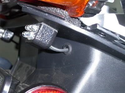
I mounted the lights in about the same area as the picture on Bounce's site. I was tempted to rout the wiring for each of the lights through the gap between the upper fender and the tail light assembly. But that route looked a little risky in terms of long-term wire abrasion, so I ended up drilling a small hole (about 7-8 mm) on each side of the upper fender, exiting in the upper corner of the under-seat area where a u-lock might be stored. By adding a neoprene grommet to each hole, I ended up with a neat, non-abrasive and nearly weather tight setup.

If I can get some good pictures, I'll add them to this post.

Again, thanks for all the help!

 
Finally, here are some pics of the H/L install. First, I mounted the H/L's and routed the wiring through the grommets. H/L instructions say that the lights must be mounted level, on a horizontal plain. Nevertheless, given the conspicuity of these lights, I decided that the slight up-incline of the mounting surface that I selected should work just fine.

WiringGrommet.jpg


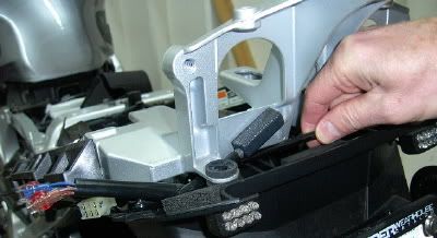
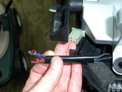
Next, having removed the tail light assembly, I routed and loomed the wiring along the rear of the interior storage area, to exit on the left side of the bike near the stock rear lighting connector. Note in the center of the first of these two pictures is the flasher module, angled downward at about 45 degrees. This angle allowed the flasher wiring to clear the frame nicely. I cut the brown and blue wires to length and connected them per the instructions with the 3-way connectors that were provided (second picture). I then snipped the green wire loop, taped each end, tucked the two ends into the loom and then tucked the loomed assembly of brown, blue and green wires into and out-of-the-way spot along the outer wall of the storage area. (Snipping the green wire causes the flasher to go to solid after 5 seconds. This feature is owner optional.). Finally, I routed the red and black wires through a separate loom (my "looming is actually heat-shrink tubing) to the appropriate pins of the rear lighting connecor, also visible in both of these photos. Once the black and read wires were attached, per Bounce's suggestions in an above post, I taped the conector wiring to stabilize everything, reconnected the connector and tucked everything away.

Loomedwiring.jpg


Tri-ConnectorsforBlueBrownWires.jpg


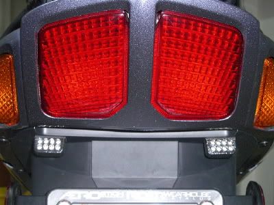
Here is the finished appearance.

HLCompleted.jpg


Thanks again for the help, Bounce!

 
Top