2009 FJR1300 AE R/R to Battery 10 Gauge Wire Harness Installation

Yamaha FJR Motorcycle Forum

Help Support Yamaha FJR Motorcycle Forum:

This site may earn a commission from merchant affiliate links, including eBay, Amazon, and others.
Joined
Aug 31, 2014
Messages
23
Reaction score
0
Location
California
Hi All,

I have a 2009 FJR1300 AE and I have been working with Brodie, ionbeam, and Donal (plus reading lots of posts on the forum) to solve electrical problems.

I am currently installing a 10 Guage regulator/rectifier-to-battery wiring harness made by RoadsterCycle.com. I made a temporary install of the harness (running outside the faring and over the tank), and I verified that it solves my voltage drop problem.

I am not sure about the best way to run the 10 gauge wires from the R/R to the battery. I am particularly concerned about whether the wires can be in contact with the engine because of heat, and how to keep the wires clear of the front fork turning radius.

I see two main options:

1. Run the wires along the left side of the bike between the engine and the frame. I think this is where the factory harness runs, but I don't see an easy way to get across to the battery compartment, and I don't see how the factory wires from the R/R get there. I am also concerned about heat from the engine, since the wires can end up being in contact with valve cover.

2. Run the wires along the right side of the bike between the engine and the frame. I see three ways to cross over to the right side of the bike

a. Loop under the R/R and leave the wires hanging loose in the center of the bike.

b. Loop back over the top of the R/R. The R/R will support the wires but exposes them to the substantial heat (about 180 deg F) from the R/R

c. Loop up and run through the area under the seat (where many people mount power blocks). This will involve cutting a hole in the plastic on each side.

Has anybody figured the best way to do this? Is there a link you could refer me to?

Thanks!

 
Last edited by a moderator:
When I fitted my cruise control on my '10, I had to run a vacuum pipe from the left to the right of the bike, it laid right over the top of the RR. You could run your wire over the RR, up the right side, far enough to pick up the "official" loom that runs between front and back along the right side of the bike. This goes up into the battery area. No "hot" bits.

Some illustrations: (click on image for larger view)

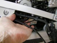
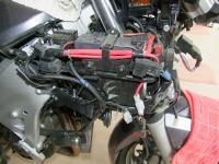
This is a view from the right of the bike. Dead centre you can see the RR, my middle finger has the vacuum pipe that goes from left to right of the bike.


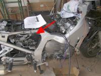
You can run the wire up from there, then ...

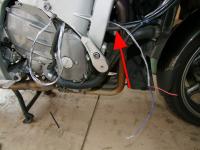
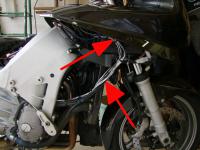
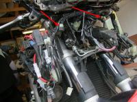
These next three show where I ran my wires between front and back, they are the ones I've covered with silver tape, so easy to see.


You will need the plastic off to do this, but for me, it's the best route.

 
Last edited by a moderator:
Thank you, mcatrophy!! I've already have the side panel off, and this will work perfectly for me.

I have a couple of questions regarding the fourth picture, which shows the forks and has two red arrows. At the 4 o'clock position from the top red arrow is a single spade connector which shows a small bit of the red wire that runs up to the battery. Where does the wire from the other half of this connector go? (To the fuse block main fuse? Back to the R/R?). Also, touching the red-wire connector is a two-wire connector (blk & blk/grn). There are two of these with only one visible in the pic. Are these two of the famous ground spyders? If yes, which two are they? (What are the Sx numbers from the famous spyder wiring diagram).

When people install a parallel wiring harness from the R/R to the battery, as I am doing, what do you do with the connector that used to go to the R/R. I am thinking I will tape it carefully, so water won't get in, and tuck it out of the way somewhere.

 
Last edited by a moderator:
Not fully sure which wire you're referring to.

Possibly this picture (of my '06) will clarify?
(Click on image for larger view)


The obvious red wire is the main feed from the battery (via the starter relay) that goes to the main fuse. The adjacent connector (green/blue and black?) I think is for the front indicator.

[edit] If you can see the wire colours, that would help in identification. [/edit]

As for spiders, none are visible in the previous pictures, try following the pictures around this one:


Last edited by a moderator:
Thanks for the suggestions sme and Chuck35. sme, the thermal sleeving looks outstanding!

Chuck35, your suggestion has benefits and possible risks. The benefit is that the factory leads from the R/R to the battery are already in place, so cutting off the large plastic connector and using the wires to power a fuseblock (or positive and negative power distribution blocks) makes perfect sense.

The risk is that the reason we are running separate, larger gauge wires from the R/R to the battery is because there is a problem (which we cannot isolate) with the factory wires. In my case there is a voltage drop of 1 volt in those wires (14.2 V at the R/R, 13.2 V at the battery). In other posts, ionbeam has pointed out that the voltage drop is proportional to both the resistance and current in the circuit. Brodie and ionbeam have pointed out that resistance can be caused by defective wiring and/or corroded connectors. Brodie, in his ground spyder writings, has mentioned that if resistance increases significantly, you run the risk of thermal meltdown. Brodie found original factory wiring that was discolored and degraded. Others have mentioned water wicking into the wires and causing corrosion.

I would suggest that if a person wanted to use the original wires to power a fuse block, the minimum test would be to turn all connected farkles on and check the voltage between power and ground at the fuse block. IMO, if this is significantly less than the voltage across the battery, it would be better to run another set of wires from the battery to power the fuzeblock.

 
mcatrophy, your pictures are outstanding!!

The layout on your '06 A looks different from my '09 AE, but I can ask my question based on your bike. On your bike the heaviest red wire runs from the battery to a black 90 deg. connector at what looks like the starter relay you referred to. A second, smaller red wire comes out of the starter relay runs forward through a black sleeve. It looks like it then curves down behind a black connector and connects to a white single terminal connector just above the lower part of the right fork tube. I assume that all power from the battery to the bike through the factory harness runs through that wire (with the exception of the starter motor).

My question is where does that wire go? On my bike it goes down and seems to disappear towards the rear of the bike. I assume that it goes, as you have mentioned, to the main fuse. On my bike, like yours, the main fuse is up and toward the front -- in your picture it is the small red box in front of the battery. So how does this red wire get there, and are there any connection points in between? I am concerned because any length of wire between the battery and the main fuse is can cause a major meltdown if it shorts and this wire seems vulnerable. But my main reason for asking is that I am looking for corrosion. I had a one volt drop between the R/R and the battery, the red wire is suspect, and I am trying to trace its connection points to find the source(s)..

My second question is regarding the ground circuit. I am working my way through each of the ground spyders, and I have cleaned the ones shown in your picture. To me the name "spyder" makes sense because of the shape of metallic piece under the black caps shown by the arrows in your second picture. These connectors have only one side. However Brodies spyder harness instructions seemed to involve unplugging ground connections that had two sides, and I am wondering if those connections are also called "spyders." One of those is shown in your first picture. It is a white two-wire connector about 1 inch behind and below the single-wire connector for the red wire we have been talking about. It has two wires connected to it, one is black and one is black/green. I see these at many places around the bike. Is this called a spyder, and/or is it part of the ground circuit?

I have pulled the large lower front panels on my bike and the rear side covers. I have also pulled the A, B, C, and D covers on the left and right. So far I hope to not pull the nose cone.

 
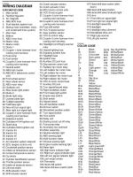
I have a wiring diagram on my site for the UK '06 "AS", equivalent to the US "AE", but with slightly different lighting arrangement and an immobiliser (probably nearer the Canadian variant). Start on this, which is the wiring diagram key:

(Click on image for larger view, click on larger image for the full picture. Bear in mind that the full picture can be quite a large file and may take a while to download)


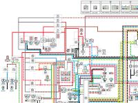
The next image shows the battery, RR and (most?) fuses:


You can follow the wiring diagram in the next few images, click "next" on the larger image.

The red wire runs to fuses reference 6, 7 and 76, which are the backup fuse, the main fuse, and the YCC-S motor fuse respectively. I expect the latter is the one that disappears towards the back of the bike.

That connector with the black/green and black wires looks like the "final ground" for the bike. The black/green connects through to a black/white that goes back to the ABS hydraulic unit. I don't think this connector gives problems (someone will probably weigh in if it does).

The "normal" 6-pin ground connectors (only called spiders on this forum except where it's been spread to others): I've shown most of them in this post, again from my '06. There may be minor changes with your '09, e.g.the interlock relay unit is centre front behind the headlamps in the '06, that was moved at some stage to under the seat???

Hope that's off some help.

[edit]

Comment on that black/green wire. I've just looked at my Haynes workshop manual. This shows a slight difference between the 2006/7 and 2008 onwards. The black/green, black and black/white wires may be arranged differently, but are still associated with the main ground connection. Or it could be that the Haynes diagram is wrong in one or the other (I've found at least one error on one of their diagrams).

[/edit]

 
Last edited by a moderator:
mcatrophy, thank you for the clarifications on terminology and for the additional information. I am in the process of going back to the wiring diagram to sort out your comments with what I am seeing on the bike.

I should have mentioned that I have wiring diagrams, both for the 2009 A and the AE. I am in the process of transposing the words on the key (i.e., "R/R," "ABS Rly") to a printed copy of the diagram. As there are 118 separate labels on the wiring diagram, this is a tedious process, but I am slowly learning what is what.

This is an important question: as far as people know, is every connector that exists on the bike actually shown on the wiring diagram? Sometimes it seems I can't find something, so I want to know if I just need to look harder!!

The reason Im asking, "Where does this wire go?" for a few critical wires is that the direction of the wire is traveling on my bike seems to be at odds with the wiring diagram. Also, from my limited knowledge, because two objects are connected on a wiring diagram does not necessarily mean that they are connected *directly.* For example, they could be connected through a power distribution point which may or may not be shown on the diagram.

For those who are interested, please look at my new posting about voltage drops and the fuse blocks. That focuses on my next set of problems.

 
Last edited by a moderator:
Almost all connectors are shown, some more obviously than others. The ground "spiders" are not shown.

Some of the less obvious are shown by letters on the wires, for instance, in the part-diagram shown in my post above, to the right of the YCC-S MCU (55), four of the wires have a circle with the letter 'A' on them, these correspond with the connector drawing shown at the top of the diagram labelled, would you believe, 'A'.

Where wires are simply shown joined, I don't know whether they have real connectors or are joined where they are common at a connector/relay or whatever, or are spliced within the loom, though I suspect not the latter.

 
OK, thanks!! I was wondering about the ground spiders. I'll be working on the bike this afternoon. I think I'll put it together and worry about the low voltage at the fuse blocks another time.

 
Top