Audiovox CCS Install Question

Yamaha FJR Motorcycle Forum

Help Support Yamaha FJR Motorcycle Forum:

This site may earn a commission from merchant affiliate links, including eBay, Amazon, and others.

BullCBX

Well-known member
Joined
Jul 12, 2005
Messages
195
Reaction score
16
Location
Loganville (Atlanta) GA
This question concerns a GEN-I (2004) bike.

I working thru the CCS-100 install this weekend, I do not have a clear understanding of the in-line check valve and the reservoir piping. Can someone offer an explaination? I have searched several past threads where people have stated to use a check valve but I really cannot put my head around this concept. Any replies would be greatly appreciated.

BullCBX

 
Bull, the vacuum is not generation specific, so one size fits all.

I went looking for a spiffy diagram I once had, but couldn't find it-

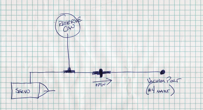
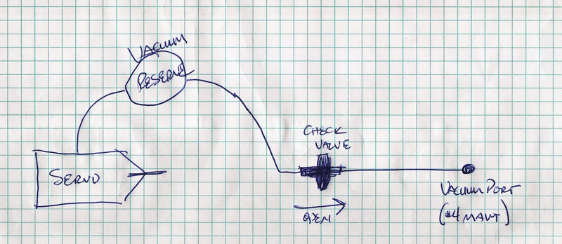
so I grabbed a quad ruled pad, a leaky pen, and scribbled up some heiroglyphics for ya -

There's two similar but slightly different ways to do this -

The most direct -

301798682_DDCqj-L.jpg


or, if your vacuum can has an in - out -

301798561_MgVRx-L.jpg


Hope this helps -

 
That is MOST helpful. The first illustration was the way I was going to run it. I guess I still do not understand the function of the check valve but I'll give it a try. I just put everything back together to give it a try and found my star lockwasher extended just far enough past the tang to keep it from idling. Back out to the garage to get the tank off and try this again.

Thanks again for the illustrations.

BullCBX

 
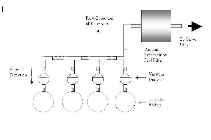
Hal's drawing is basically all you need, I'm adding another drawing showing how to tap multiple throttle bodies (just because I have it and it was handy). You are tapping the intake throttle bodies where the flow is critical to the induction process. When you tap onto a TB port you are creating a small leak. With a vacuum diode the leak is controlled in only one direction, once the accumulator (vacuum reservoir) has the same vacuum level as the TB the diode will close. When your bike goes up hill or power is asked for, the vacuum level in the TB will decrease (become closer to atmosphere), under this condition the diode will close. This both keeps the vacuum accumulator from interfering with the TB flow, and it also allows the vacuum in the accumulator to be retained for cruise control function.

While some run their cruise without any diode, some run without an accumulator, I feel that it is a good practice to have both the diode and at least some small accumulator. Without this the engine will be running as if the Throttle Body Synch is off in one cylinder or worst case, running too lean which can lead to burned valves or burned pistons :eek:

AVCCThrottleBodyConnections.jpg


Some of the best engineering done is napkin engineering :lol: Good job Hal!

 
Last edited by a moderator:
Thanks for the additional explaination. Everything is back together and I look forward to giving it a test tomorrow morning on the way to the office. Thanks again.

BullCBX

 
I have even used 5 check valves, one at each port and once at the reservoir for backup if one of the port check valves failed, overkill I think.

For class discussion:

Compare and contrast the pros and cons of 4 check valves versus 1 check valve.

 
I have even used 5 check valves, one at each port and once at the reservoir for backup if one of the port check valves failed, overkill I think.
For class discussion:

Compare and contrast the pros and cons of 4 check valves versus 1 check valve.
OCD?

 
Well, I cannot comment on which set-up is better, but I can say the single valve set-up to a single port appears to work for me. Rode the bike into work this morning and the CCS worked like a charm. Up and down several good sized hills and the throttle was even and smooth. A big thanks to all those who posted details of their own installations. I do not think I would have tried to accomplish this task without all of the information from this group.

BullCBX

 
Top