1. Thanks to everyone who put the procedures together for Gen II
2. There were a couple of photo captions on the Gen I writeup that showed a jumper resistor and (in a different photo) a jumper wire. This was called the Barbarian *Jumper* mod.
3. However, in the Gen I writeup, there was a lot of detail about getting the pin out, and swapping the wire from one hole to another, but essentially no writing about installing the jumper. Just those photos.
4. Now on the Gen II writeup we have no mention of jumpers between pins, just the swap. In a document that seems extremely thorough and well-done.
Questions:
A. Is "jumper" a misnomer?
B. Was there any jumpering on Gen I?
C. If there was jumpering on Gen I, why no text about it?
D. If there was no jumpering on Gen I, what are the two photos about?
E. If there is jumpering on Gen II, why isn't it in the writeup?
...If you preform the mod, change the settings, then reverse the mod, does it revert to the original settings or are the new settings 'locked' in the memory?
First, John from 11/08:
1. (yes, thanks to all for the Gen II instructions)
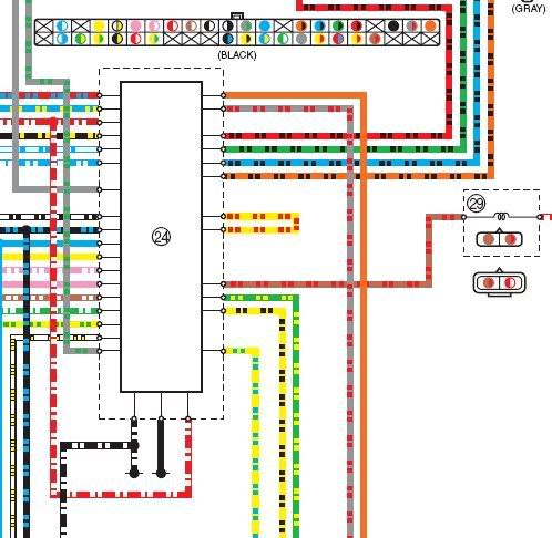
2. The early Gen I's had a Yellow/Red wire that was in a jumper configuration on the ECU connector. The picture from the Gen I ECU connector in the procedure makes it look like there are two different Y/R wires, but in fact the Y/R wire is a jumper. One end of the jumper was moved to enable the CO diAG screen. You can see the Y/R jumper in the ECU schematic below (item 24). Just above the ECU you can see the connector with the Y/R wire in pin location 25 & 27 and the plug in pin hole 29 (the X) (located bottom row, right end).
3. The later Gen I's like my '04 did not have the Y/R wire at all. I sent pictures and instructions for H. Marc to post along with Torch and Barbarian's how-to.
H. Marc only paraphrased my instructions and didn't include verbatim details. As there was no Y/R wire a jumper at all, a jumper had to be made then pushed into the holes at pin #25 & #29. Being a pioneer on later Gen I Barbarian Jumpers I chose to use a 22k resistor to ensure that no mater what the ECU would not be harmed. In the text that did not make it to the FJR1300 tech article I stated that it was OK to use a piece of wire in place of the resistor. The new wire would work better if it were stranded, and the ends should be stripped to a surprisingly long 1/2" to reach all the way into the female sockets in the ECU side connector. I additionally suggested tie-wrapping the jumper to adjacent wires to hold it in place in addition to the locking white clip that is part of the connector.
4. The Gen II does not have a jumper, only one wire that gets moved to enable the CO diAG screen. When the Y/R wire is placed in pin hole #25 the voltage on the Y/R wire tells the ECU to enable the CO screen.
A. The '03 had a jumper and it was called out correctly in the original how-to. The '04 did not have a jumper
or wire and a jumper had to be fabricated.
B. The Y/R jumper already existed in the '03 (see # 2. above)
C. There is no jumper associated with the Gen 2 ECU, only a single wire to be moved.
D. Already explained about the jumper in # 4. above.
E. No jumper so no explanation.
==========================
FJRGuy:
The CO values are held in permanent memory in the ECU, once the values are set or changed the ECU will retain them even if the battery is disconnected. All the jumper wire or wire relocation does is enable the CO Setting Menu on the diAG screen. You
could remove the jumper after altering the CO values and all would be OK. But, why remove the jumper, if it isn't hurting anything?


