Datel vs Kuryakyn LED voltmeter

Yamaha FJR Motorcycle Forum

Help Support Yamaha FJR Motorcycle Forum:

This site may earn a commission from merchant affiliate links, including eBay, Amazon, and others.
As I understand the charging system, the FJR has a stator and shunt-regulator/rectifier. Unlike an alternator or series controlled (blocking) stator, the FJR stator supplies its full output at all times. If the power is not used by accessories, it is shunted to ground by the switches in the R/R. If the power is all consumed by accessories and bike loads, the stator works no harder, you just enter a net discharge scenario. If you are running no accessories the net surplus power is shunted to ground which has no effect on the stator, but does create heat in the R/R and may increase heat in the stator.

What am I missing?
Explode.jpg


The issue is voltage drop.

The Gen I electrical system is designed to maintain 14.x volts up to 490 watts of power consumption (35 amps) and the Gen II should maintain 14.x volts up to 590 watts (42 amps). Once the electrical system draws more current than design, the voltage starts to drop. There is a fundamental voltage, current, load (resistance) law of electricity (Ohm's law). The values react in specific ways such that in the case of increasing load, current will go up but it forces voltage to go down.

Riding along with the DATEL showing 14.0 volts the R/R is shunting excess power to ground. Turn on the driving lights, the R/R stops shunting power to ground because the electrical system is consuming ALL the power generated, and the stator can just maintain 14.0 volts. Now turn on the heated grips. Voltage on the DATEL drops to 13.4 volts, the R/R is off allowing 100% of the stator's output to pass. Where did the voltage go? There has to be a voltage drop someplace. The voltage drop happens in the stator; the stator trades voltage for current. The byproduct of this drop is heat increase within the stator proportional to the voltage drop, or conversely said, heat increases proportional to the current increase. The heat is generated in the stator windings and concentrates where there are wire connections or wire insulation break down. This is why the Electrosport stators almost always show failure in the same place -- where the stator winding wires bond to the wires that exit out of the stator at the top lobes of the stator core. The lower the voltage goes the more heat that gets generated within the stator. The voltage drop is most accurately measured directly on the output pins of the R/R to eliminate and voltage drops caused by harness connections. The lower the voltage at the R/R output the hotter the stator runs.

I'll give this explanation a rethink tomorrow after our Parker's Maple House breakfast run and clarify this if needed after that.

 
Last edited by a moderator:
Sorry - Another alternative to consider to make it even tougher :rolleyes:

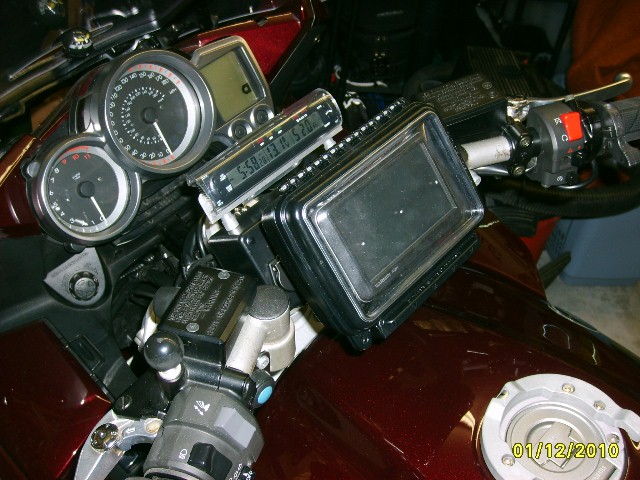
I used the Kuryakyn for a while and found the "bar graph" LED readout doesn't offer enough resolution so I tried this one (Full Details Here). I feel the 1/10V resolution is fine. There are a couple of issues with it, but I've been happy with them on the bikes. The thing I like best is they draw such little power that I have them displaying time/voltage/temp all the time, even with the bike off.

4446727166_6f6f3b8602_o.jpg


Last edited by a moderator:
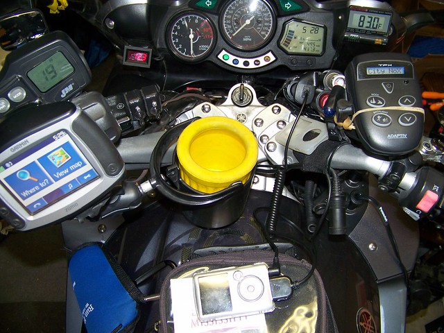
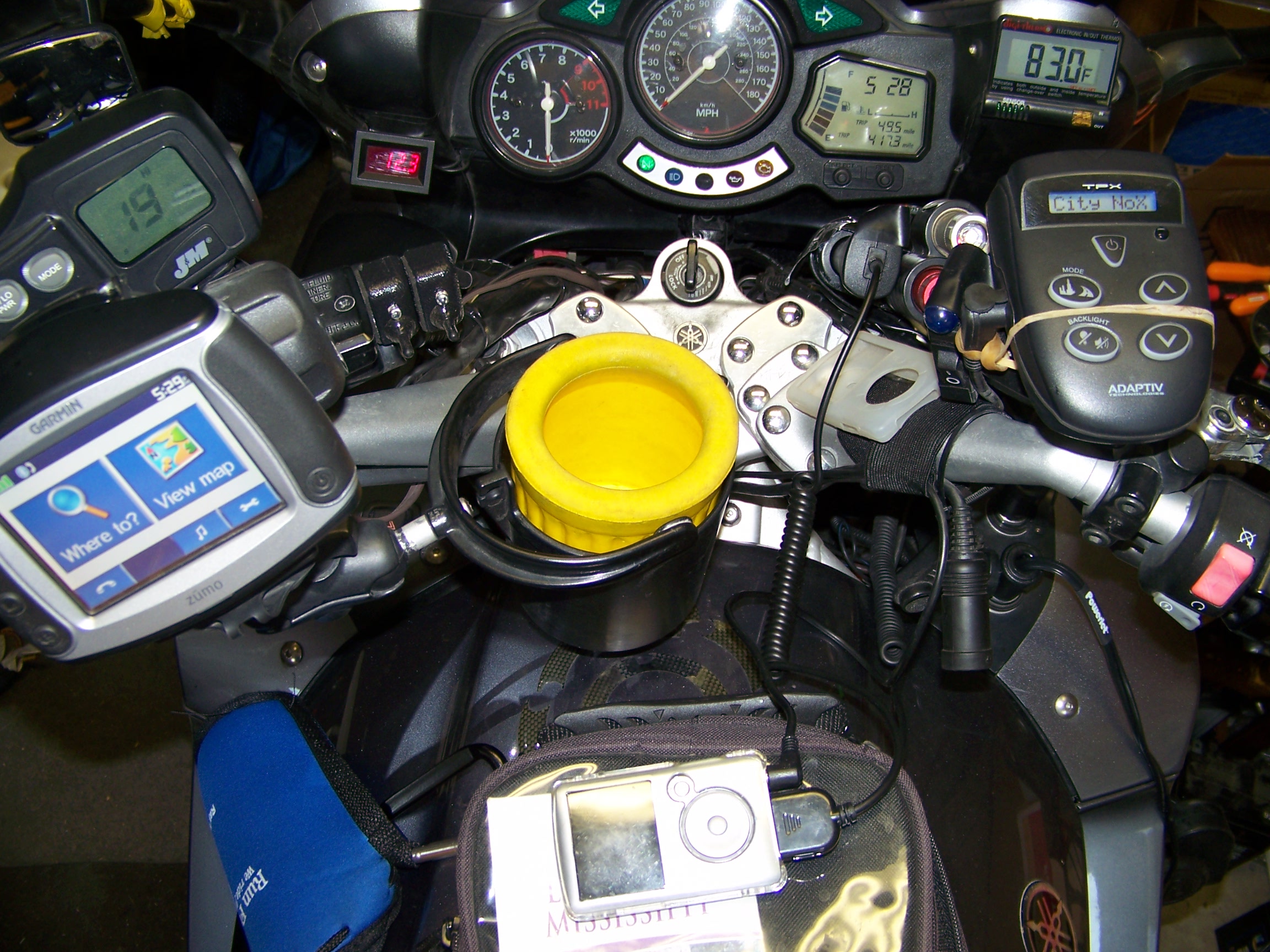
I have BOTH on the bike

The first green led on the Kury went out

When working normally, the next green will light so all OK

But I don't look at it anymore...just the datel with .1 ... about 6 mo after install

I added a relay with leads directly to battery terminals and switched off the key at one end of a toggle, and always on on the other

The toggle can turn stuff on as always on, or turn stuff off to ignition key switched including the voltmeter, CB, AVCC, and Zumo GPS

works great for me

3708483364_2db01fa377_z.jpg


Last edited by a moderator:
Sorry - Another alternative to consider to make it even tougher :rolleyes:

I used the Kuryakyn for a while and found the "bar graph" LED readout doesn't offer enough resolution so I tried this one (Full Details Here). I feel the 1/10V resolution is fine. There are a couple of issues with it, but I've been happy with them on the bikes. The thing I like best is they draw such little power that I have them displaying time/voltage/temp all the time, even with the bike off.

4446727166_6f6f3b8602_o.jpg
Yea, saw that one. But the FJR already has a clock and temp gauge. Although it is all visible at the sametime. I may use that for my Valkyrie.

Rich

 
I have BOTH on the bike

The first green led on the Kury went out

When working normally, the next green will light so all OK

But I don't look at it anymore...just the datel with .1 ... about 6 mo after install

I added a relay with leads directly to battery terminals and switched off the key at one end of a toggle, and always on on the other

The toggle can turn stuff on as always on, or turn stuff off to ignition key switched including the voltmeter, CB, AVCC, and Zumo GPS

works great for me

3708483364_2db01fa377_z.jpg


Thanks Mike! Nice setup! Is your Datel mounted in the dash on on the outside? Hard for me to see in the pic.

Rich
 
As I understand the charging system, the FJR has a stator and shunt-regulator/rectifier. Unlike an alternator or series controlled (blocking) stator, the FJR stator supplies its full output at all times. If the power is not used by accessories, it is shunted to ground by the switches in the R/R. If the power is all consumed by accessories and bike loads, the stator works no harder, you just enter a net discharge scenario. If you are running no accessories the net surplus power is shunted to ground which has no effect on the stator, but does create heat in the R/R and may increase heat in the stator.

What am I missing?
Explode.jpg


The issue is voltage drop.

The Gen I electrical system is designed to maintain 14.x volts up to 490 watts of power consumption (35 amps) and the Gen II should maintain 14.x volts up to 590 watts (42 amps). Once the electrical system draws more current than design, the voltage starts to drop. There is a fundamental voltage, current, load (resistance) law of electricity (Ohm's law). The values react in specific ways such that in the case of increasing load, current will go up but it forces voltage to go down.

Riding along with the DATEL showing 14.0 volts the R/R is shunting excess power to ground. Turn on the driving lights, the R/R stops shunting power to ground because the electrical system is consuming ALL the power generated, and the stator can just maintain 14.0 volts. Now turn on the heated grips. Voltage on the DATEL drops to 13.4 volts, the R/R is off allowing 100% of the stator's output to pass. Where did the voltage go? There has to be a voltage drop someplace. The voltage drop happens in the stator; the stator trades voltage for current. The byproduct of this drop is heat increase within the stator proportional to the voltage drop, or conversely said, heat increases proportional to the current increase. The heat is generated in the stator windings and concentrates where there are wire connections or wire insulation break down. This is why the Electrosport stators almost always show failure in the same place -- where the stator winding wires bond to the wires that exit out of the stator at the top lobes of the stator core. The lower the voltage goes the more heat that gets generated within the stator. The voltage drop is most accurately measured directly on the output pins of the R/R to eliminate and voltage drops caused by harness connections. The lower the voltage at the R/R output the hotter the stator runs.

I'll give this explanation a rethink tomorrow after our Parker's Maple House breakfast run and clarify this if needed after that.
I have been dealing with a chronic failure in stators in 05 to 07 Suzuki C90 cruisers for a number of years. The OEM stators farily reliably failed between 16000 and 20000 miles by burning through insulation at the top poles of the stator near the connection exiting to the R/R, resulting in the stator shorting to ground. No specific pattern was found relating the excessive use of accessories to the failures, but like the Gen I FJR this unit only put out 38 amps at 14 VDC, and with losses considered only netted 480 watts of power, much of that consumed by the fuel injection, lighting and ignition.

The "exploding head theory" is kinda new, and it is a logical explanation for the failures, and would seem to point to increased frequency of stator failures amongst heavily farkeled bikes. Not sure if that correlation has been made with the FJR. What we did find to be an effective solution was to change to a series regulator (Cycle Electric CE602) which is rated for 38 amp, 3-phase stators. I suspect a similar fix would improve life on a FJR stator, but the OEM stator seems to do pretty well, while the "hotter" electrosport stators seem prone to failures. I witnessed the death of Madmike2's ES-stator in Death Valley, and it wasn't a pretty site. Have you done any work with series regulators as a possible solution?

 
I ran my battery down resulting in a huge waste of valuable sleep time when at the next bonus location I had to spend 25 minutes attempting to push start the bike after the battery wouldn't.
I can attest to how twitterpated this makes him....he yammered for a good 20 minutes about before we finally got to sleep in Campbellton.
He'd find something to yammer about for 20+ minutes regardless of his state of twitterpation :p .

Ditto on the Datel. Just bought a second one for my second FJR...went with the 0.1 variety myself but 0.01 would be fine too.
+1

 
Explode.jpg


I have been dealing with a chronic failure in stators in 05 to 07 Suzuki C90 cruisers...The OEM stators farily reliably failed between 16000 and 20000 miles by burning through insulation...this unit only put out 38 amps at 14 VDC...much of that consumed by the fuel injection, lighting and ignition.

...What we did find to be an effective solution was to change to a series regulator (Cycle Electric CE602)...I suspect a similar fix would improve life on a FJR stator, but the OEM stator seems to do pretty well, while the "hotter" electrosport stators seem prone to failures...
Stator design and construction is part hard number engineering and part art. Yamaha has one way of making the laminated core, specifying the winding wire gauge plus insulation material and the art part – how the core gets wound. If you examine the Yamaha stator, the Electrosport and Rick's Motosports Electrics stators you will find that none are wound alike. The winding can have a significant performance impact. The wire insulation will have a significant reliability impact as well as affecting mechanical winding methods. Certainly cost plays a role too.

Yamaha has found a design and materials that let the stock stator run into overload without breaking down or failing. The design is capable of withstanding full output, 100% of the time in harmony with the R/R that shunts unused power to ground.

Electrosport's stator generates 17% more power than the stock stator and must attempt to withstand having 100 watts more shunted to ground all the time. The ES stator has to do this in the same physical space and with the same cooling as the stock stator. The stock stator sees a continual load of 490 watts whereas the ES must withstand a continual 590 watts being used by a combination of live load and the R/R dumping power to ground.

The OEM Yamaha R/R shunt design will force any stator to put out 100% power, 100% of the time. When the electrical system draws more current than what the stator can supply the stator output voltage drops. The drop occurs within the stator and the stator gets hotter in proportion to the voltage drop.

With a series R/R the stator will run cooler because it is only being asked to supply the actual current being used. There is still a voltage drop, but the drop is now occurring in the R/R. Note that the CE R/R is big and mounted to stand way up in the air to allow 360º cooling air in order to handle all the dissipated power. Once the motorcycle's electrical load exceeds the design limit of the stator, the stator voltage will drop within the stator just like the OEM setup.

The charging SYSTEM is actually composed of the fixed stator as well as the spinning magnetic rotor and the R/R. To get more power practically, the stator should gain more wire (diameter and/or length) and the rotor should have stronger magnetic fields (size or better magnets), and if allowable more rotation speed. The charging system has to produce some minimum amount of current at idle to handle the normal current demand of the basic running systems. At idle the OEM R/R is not shunting much if any current to ground. Once up to running speed/RPM the OEM R/R will begin shunting more excess current to ground.

 
Last edited by a moderator:
Late to the game but for those of us that are red/green color blind (to various degrees) the LED type meters don't often work very well. Even getting to know the positions of the 3 different lights (low/medium/high) doesn't always work in anything other than complete darkness. Being able to read actual numbers does work. It also gives you more information and is why dash lights, in place of actual gauges, in cars were named "dummy lights" when they first came out,

 
Just a minor note on this thread - power is current squared times resistance. The resistance of your stator can be considered to be fixed in this equation (it will change a little with heat, but not too much). Going from 32A to 36A works out to being roughly a 25% increase in heat in that system. If you go up to 40A, heat will go up by more than 50%. This may be part of the reason why the shunt regulator is there. Beyond a certain point, you would simply be drawing too much current across the fixed series element of the shunt regulator, and once you're past that threshold, the battery will do its best to supply what you need.

Normally, I would dump the shunt reguator for a series regulator, but there are artisans in Japan with some pretty amazing magnetic winding/design skills, and I would be uneasy tossing out Yamaha's design in favor of something else.

My FJR isn't electrically farkled, though I plan on it. Before doing so, I will be swapping to LED headlights to free up some capacity.

 
I'm not convinced by this "voltage drop" business, which does not mean I am criticizing or dismissing it.

But the stator puts out alternating current, not direct current, and the voltage is quite high. The bit I am not sure about is the suggestion that the voltage out of the stator drops, or that a drop in AC would cause the over-heating.

It seems to me that the obvious place there might be a problem is not in the stator, but in the rectifier that converts the AC to DC.

Whatever, I'd like to see a fuller explanation if anyone has any links, because this is the first time I have heard this one :)

Generally it wouldn't matter, but some of us find ourselves carefully balancing the load on the system, especially at night and when it is cold. I find myself watching the voltmeter like a hawk!

 
Once the shunt regulator is out of the equation (SCR's not conducting because the monitored voltage is too low), you are down to the voltage dropped across the diodes, and the heat generated within the stator itself. The diodes have a pretty predictable voltage drop, and the modern ones tend to drop about the same amount of voltage regardless of current (to a point). The stator, on the other hand, is resistive, so the power dissipated increase significantly as more current is drawn.


Latest posts

Top