dcarver
Well-known member
Need help on alternator theory of operation...
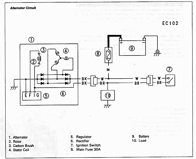
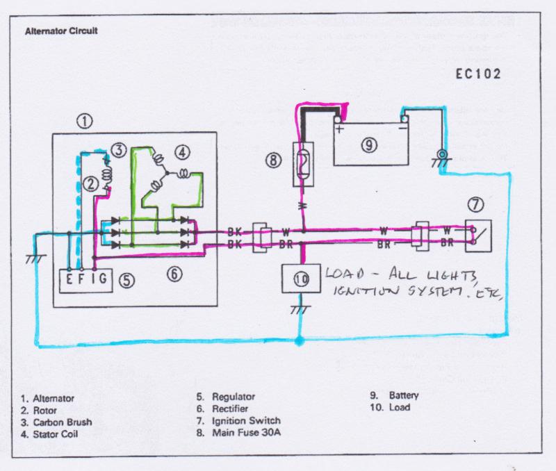
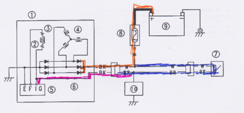
Looking at the schematic, is this how it works?
- Closing switch (7) provides current making EMF across rotor coil (2).
- Rotor (2) rotates, crossing flux lines of stator (4), creating 3 phase ACV
- Rectifier (6) converts ACV to DCV
- Regulator (5) regulates to acceptable levels
- The ‘BR’ wire is the load (lights, ignition, etc)and should be 13.5 – 14.x volts?
- The ‘W’ wire should be, essentially, battery voltage?
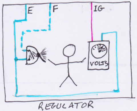
- ?? How does the alternator sense battery voltage to change field current, EMF flux magnitude across rotor coil (2)?
- If Alternator (1) is ungrounded, how would that cause max output voltage (per tech's statement?)
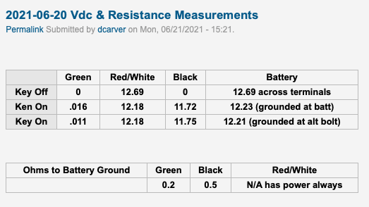
Tim's CBX sells refurbished Kawi Zx7 alternators with adapter plate. More juice, oem alt is CBX Achilles heel. Ordered, arrived, installed, vdc at battery too high, approx 17 vdc.
Sent it back, Tim's took to their repair shop, it tested fine, but installed new regulator, just for insurance.
Sent back, arrived, installed, > 19 vdc on my CBX. Send back to Tim's, repair shop, works great in test fixture.
Bill from Tims installed on his CBX, no problems, worked perfect.
Tech at repair shop stated alt is grounded via bolts to engine, if not properly grounded, alt would perform at max output, bypassing regulator. I use nickel based anti-seize... Could that be the problem?
https://candybuttorg.ipage.com/cba/node/1010 for entire thread, with pictures.
Thanks in Advance, Don


