FJR frame not an electrical conductor

Yamaha FJR Motorcycle Forum

Help Support Yamaha FJR Motorcycle Forum:

This site may earn a commission from merchant affiliate links, including eBay, Amazon, and others.

Constant Mesh

Well-known member
FJR Supporter
Joined
Jul 11, 2005
Messages
1,802
Reaction score
65
Location
Tenn
I'm curious why the FJR designers didn't use the frame as a return path for many of the electrical circuits.

They have a few circuits using the engine crankcase as a return -- starter motor, oil level switch, and gear indication.

On my Honda car the battery negative terminal connects directly to the nearby body sheet metal. That one large conductor is the only connection to the negative battery post.

I don't understand why they chose a negative return bus with all the daisy chained mechanical splices and their potential problems over a network of strategic connections to the frame?

Maybe there's more potential for corrosion affecting frame connections over a separate enclosed bus?

 
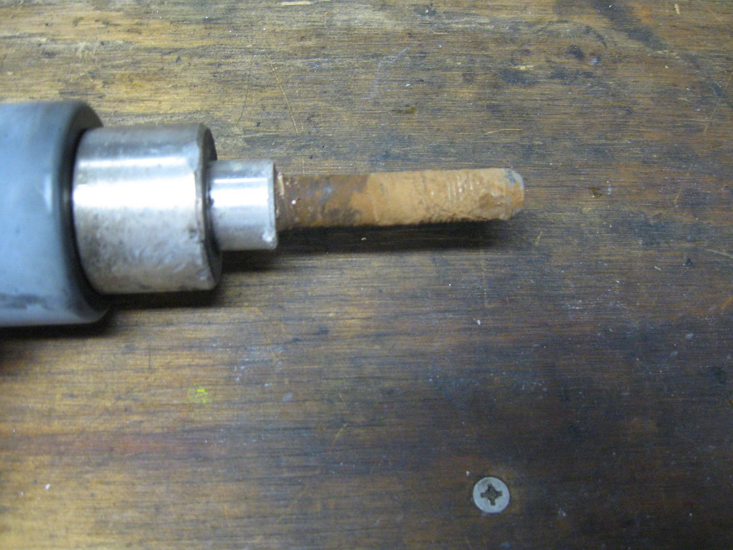
Aluminum doesn't play well when its joined together with dissimilar metals and current flows through them, especially when it's high current. That is true not only for the actual electrical connections, it's also true for any metal fasteners (bolts) that may have different current conduction characteristics.

 
Last edited by a moderator:
If you every worked on some older bike you would realize.

As mentioned above, it help stops galvanic corrosion that greatly increases when current is passes through metals.

No more bashing away on a impact driver trying to remove bolts and engine casing screws.

 
Last edited by a moderator:
I seem to remember that the main problem with corrosion was when vehicles had positive grounding?

It was a long time ago.............

 
Last edited by a moderator:
When an engineer designs a ground bus via the frame of a vehicle, he ensures that the frame has all of the electrical bonding in place necessary to provide a low-resistance return path for the electrons back to the battery B-. Aluminum is a great conductor, used in all kinds of RF and electrical applications, it's just that there are different impedances involved (required) for various circuits. Some operate at DC ground, some operate a few ohms above ground for applications such as current monitoring.

 
Last edited by a moderator:
Grounding through the frame is archaic. Many electronic devices use a change in voltage to signal an action, rather than an on-off analog signals. Varying resistances due to grounding variances can cause loss of control of an item such as radio volume, digital readouts (tachs, speedometer etc). In other words, Yamaha has transitioned to more sophisticated electronic systems that require a dependable reference voltage to accomplish normal actions.

As an example on the FJR, if you let your battery get to a low voltage, and you are attempting to start the engine, even if the engine will crank, the fuel injection system will not allow fuel flow due to insufficient voltage= no start.

 
For the analog sensors which use a regulated 5 volt DC supply they need a separate return back to the computer module. You could easily have a separate return system for those devices. These are very low current analog devices. But for most devices where precise voltage levels aren't very critical and (lighting, etc.) a return through the frame would seem reasonable.

The wiring diagrams provided in the service manuals don't provide all that much info. I would call them schematics and not wiring diagrams. There is almost no info provided about the negative return bus. All those daisy-chain mechanical splices are completely absent from the drawings.

It would be nice to know the routing of the large DC conductors from the rectifier/regulator (R/R). How is the R/R interconnected into the system? Where are the large DC conductors?

I don't know if the frame is made from the same material as the crankcase but obviously the large copper cable with terminal is bolted to the crankcase for the operation of the starter, etc.

 
The R/R wires go to the starter relay where they join the heavy battery cables on studs with nuts (so to speak
wink.png
). The top engine casting is uniform to the starter housing. Other parts of the motor and frame can be isolated by gaskets, relying on bolts for electrical continuity. Steel fasteners into aluminum, especially where water spray is present can lead to galvanic action and accelerated oxidation. A fun byproduct is frozen bolts.

Another unadvertised special of aluminum is that the rate of metal expansion is very different from copper. This expansion difference with heat is why we no longer see aluminum wiring in homes or house trailers. Without special pigtail connectors to interface the different metals heat expansion would loosen the connections resulting in repeating heat/loosen cycles that results in flames.

 
Last edited by a moderator:
You guys always amaze me. Oh, the mistakes I've made. On my first '05 FJR, I wanted to upgrade the horns, so I ordered a wiring harness (from FJRandy, IIRC) that needed to be grounded. Seeing nothing really convenient, I drilled into the frame down under the ignition a little bit and fastened the connector down with a self-tapping screw. Luckily, I wrecked the bike before the differing current conduction characteristics caused a case of galvanic corrosion.

Come to think of it, that's probably why I wrecked. Boy, I'll never do that again.
rolleyes.gif


...Luckily, I wrecked the bike before the differing current conduction characteristics caused a case of galvanic corrosion...
Of course steel bolts don't corrode in aluminum frames, just kidding
ermm.gif


FJR134.jpg


Last edited by a moderator:
I would assume that the R/R's DC+ conductor would go almost directly to the ignition switch. Most of the large currents pass through this switch and on to the fuses, etc. The ignition switch is where everything's happening once the engine is started.

Not much current flows from the R/R to the battery area. A small battery charging current and for my non-ABS '04 the fuel pump and the injectors.

It's a pity there's not a DC terminal block near the output of the R/R where one could attach accessory loads. Higher voltage there than at the battery.

After all, the R/R is the sun and source of all energy in the FJR solar system. The battery gets you started but after that it's a bit player.

 
Run a pair of 8 gage wires directly from the R/R to the battery, with a 50 amp fuse on the + wire, and you will pretty much have all the power you can get with very little voltage drop across that 6 1/2 foot distance.

Problem solved.

Brodie

😏

 
Last edited by a moderator:
Top