


War Machine
Zero Altitude Test Pilot
I knew that I would have to install a fueblock for future farkles, but waited until I purchased the Autocom & a radio. Dispite being an excellent product I decided not to use the Blue Seas Fusebox due to its sheer oversize. It was like when I used to own a Honda, excellent product but overkilled in design. I work better with Keep It Simple Stupid. I decided to use a 6 fuse Fuseblock, & Panasonic 40 Amp Relay with a wiring harness supplied by Eastern Beaver.
Here are a few pics of my installation:
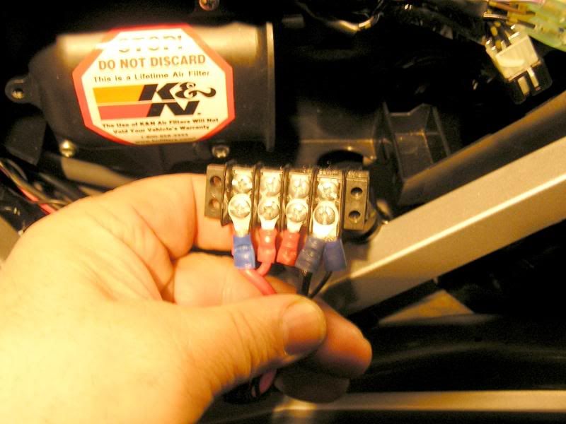
First I started with a Barrier Strip to supply a centralized 12Volt Battery Source:
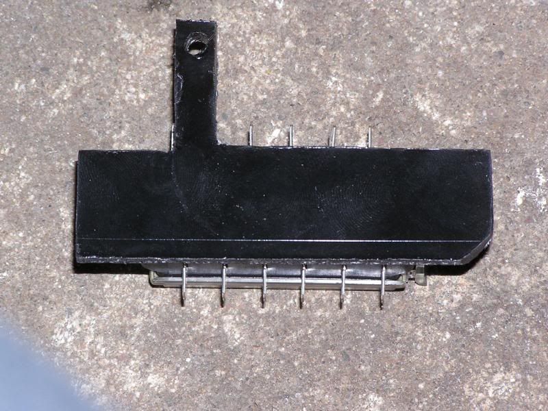
Then I cut a peice of Plexiglass as a backplate to mount the fuseblock on (The hole at the top of the plexi is to mount it to the bottom screw of the air intake cover):
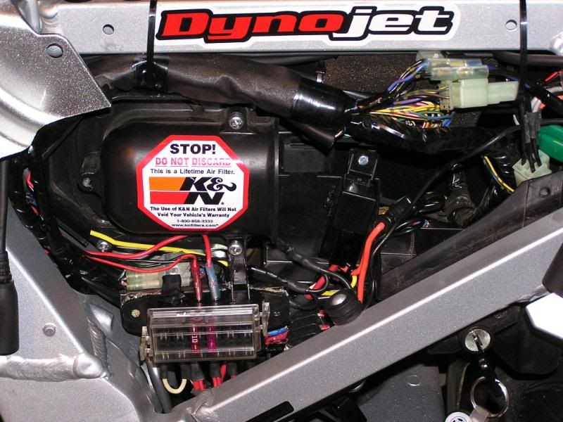
I then installed: A Panasonic 40 amp Relay, B Fuse Holder (with 30 amp fuse) C Barrier Strip. Notice the velcro strip immediately above
the barrier strip. This allows me to remove the barrier strip out of its mounting area so my big mitts can get to it in the future.
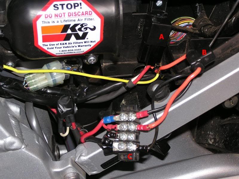
The Fuse Holder red wire supplies the 12 Volts (from the Battery) to the relay from the barrier strip. The Black wire is the negative, also from the battery via the barrier strip. (Note: It is extremely important to use a ground directly from the battery when connecting Radios, Autocoms, etc. This is the purest ground on the bike & will eliminate most interferrence problems with audio connections.) The yellow wire is the switched source for the relay (So everything isn't powered without the key on.) I chose to connect this to a white wire with a green stripe on it (08 FJR) that is connected to the heated grips controller mounted on Panel B of the fairing (Lower left) This wire for the heated grips is like the headlight relay, where the headlights won't light upon turning the key, but will light after the bike has started. I wanted the fusebox & all the accessories to have power after the bike started, that way there is 0% chance of power drain upon start up. The white & red wires supply the power from the relay to the fuseblock. The white wire allows for one fuse to be unswitched (12Volt constant).
This is what it looks like after everything is in place:
And this is what it looks like with my modified outer cover:
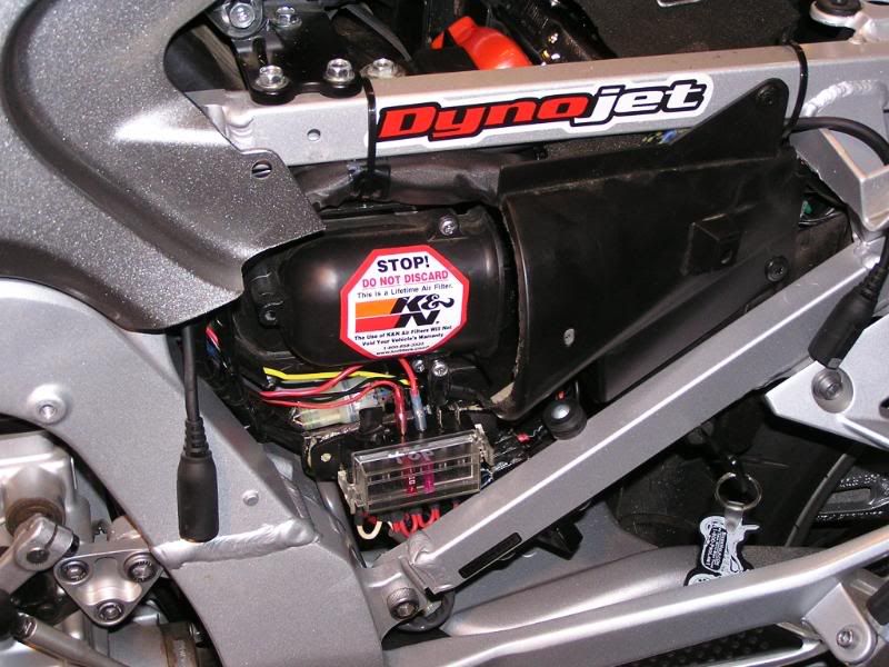
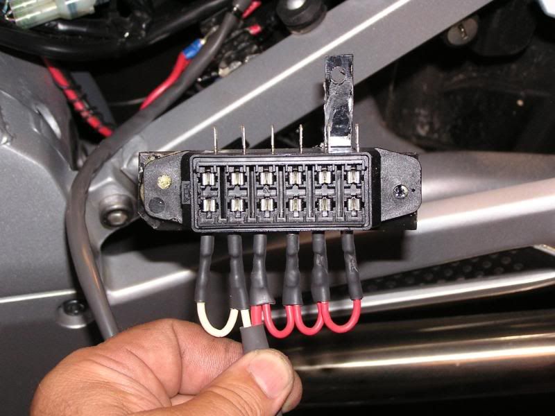
If you notice in the above pic there are only 2 fuses inside the fusebox. Thats because I only installed the Autocom & the Jensen Radio. I will install
a GPS & Radar Detector/Jammer in the future.
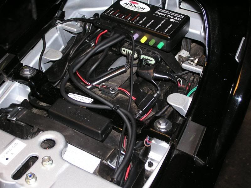
Here is a pic of the Autocom:
And a pic of the Jensen Radio:
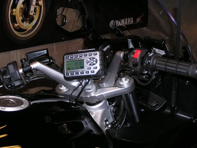
Notice the Antenna mast is installed into Panel C of the fairing.
The main reason I decided to install this fuseblock was to save space & utilize a "dead" area under the side cover, which is easily accessible. If I installed the Blue Seas Fuseblock it was so large that it would have used up the space in the tail section where the Autocom & the alarm are.
Just a new spin of an old coin.
Here are a few pics of my installation:
First I started with a Barrier Strip to supply a centralized 12Volt Battery Source:
Then I cut a peice of Plexiglass as a backplate to mount the fuseblock on (The hole at the top of the plexi is to mount it to the bottom screw of the air intake cover):
I then installed: A Panasonic 40 amp Relay, B Fuse Holder (with 30 amp fuse) C Barrier Strip. Notice the velcro strip immediately above
the barrier strip. This allows me to remove the barrier strip out of its mounting area so my big mitts can get to it in the future.
The Fuse Holder red wire supplies the 12 Volts (from the Battery) to the relay from the barrier strip. The Black wire is the negative, also from the battery via the barrier strip. (Note: It is extremely important to use a ground directly from the battery when connecting Radios, Autocoms, etc. This is the purest ground on the bike & will eliminate most interferrence problems with audio connections.) The yellow wire is the switched source for the relay (So everything isn't powered without the key on.) I chose to connect this to a white wire with a green stripe on it (08 FJR) that is connected to the heated grips controller mounted on Panel B of the fairing (Lower left) This wire for the heated grips is like the headlight relay, where the headlights won't light upon turning the key, but will light after the bike has started. I wanted the fusebox & all the accessories to have power after the bike started, that way there is 0% chance of power drain upon start up. The white & red wires supply the power from the relay to the fuseblock. The white wire allows for one fuse to be unswitched (12Volt constant).
This is what it looks like after everything is in place:
And this is what it looks like with my modified outer cover:
If you notice in the above pic there are only 2 fuses inside the fusebox. Thats because I only installed the Autocom & the Jensen Radio. I will install
a GPS & Radar Detector/Jammer in the future.
Here is a pic of the Autocom:
And a pic of the Jensen Radio:
Notice the Antenna mast is installed into Panel C of the fairing.
The main reason I decided to install this fuseblock was to save space & utilize a "dead" area under the side cover, which is easily accessible. If I installed the Blue Seas Fuseblock it was so large that it would have used up the space in the tail section where the Autocom & the alarm are.
Just a new spin of an old coin.
Last edited by a moderator:
