Brodie
Darksider #16 - and Proud of it !
Well you'll have to wait, to Buy Now since the EB site for this connector currently reads "Temporarily Out of Stock Sorry", I guess Brodie cleaned them out
Who... Me?
:derisive:


Well you'll have to wait, to Buy Now since the EB site for this connector currently reads "Temporarily Out of Stock Sorry", I guess Brodie cleaned them out
Solder is not recommended for use in vehicular wiring harnesses because it is brittle which is why everything is crimped.Step 1: Build one "5-INTO-1" repair spider connector as shown below and install it when I lift the tank to replace spark plugs. I just happen to have a spare spider and cap from the damaged portion of the front cowling harness so I can prepare the spider with ground lead prior to tearing into the bike. It wouldn't take long to make one once the bike is apart though. I will not know exactly where to ground it on the chassis until I open it up, so [SIZE=12pt]I will solder on a long length of wire[/SIZE] so I can cut-to-fit and crimp the ring terminal during installation. I'm in need of a spark plug change in the very near future so this will be an opportune time to do this step. This extra ground wire helps reduce the current flowing through spider S4-Pin3, the actual battery ground, where I believe the true trouble lies. This will eliminate a majority of the meltdown risk.
Tell people that all the time and they just won't believe me (Patriot). Allot of us don't keep vehicles long enough for it to be a problem, for us (as in me), anyway.Solder is not recommended for use in vehicular wiring harnesses because it is brittle which is why everything is crimped.Step 1: Build one "5-INTO-1" repair spider connector as shown below and install it when I lift the tank to replace spark plugs. I just happen to have a spare spider and cap from the damaged portion of the front cowling harness so I can prepare the spider with ground lead prior to tearing into the bike. It wouldn't take long to make one once the bike is apart though. I will not know exactly where to ground it on the chassis until I open it up, so [SIZE=12pt]I will solder on a long length of wire[/SIZE] so I can cut-to-fit and crimp the ring terminal during installation. I'm in need of a spark plug change in the very near future so this will be an opportune time to do this step. This extra ground wire helps reduce the current flowing through spider S4-Pin3, the actual battery ground, where I believe the true trouble lies. This will eliminate a majority of the meltdown risk.
I think it will go to the root of the problem (overload), and eliminate it at the source.Looking at the FSM wiring diagram, and looking at the wiring on the bike. It looks to me like the black wires (in the diagram) that end with one line threw the end is a spider, and where 2 wires meet to look like a splice may also be a spider.
Also I only see 3 chassis grounds.
-neg battery cable
-starter
-ABS ECU
So everything else is going threw a spider. And we know the BLACK WIDOW is the one that all other B spiders go threw. So all lights, fans, shield drive etc. are going threw it.
This is worse than I thought, because of the fans. I didn't think to check them until it was mentioned. I just assumed (I know) they would go to chassis with something like that. While we're on the subject, how many amps do the headlights and shield drive draw ?
Here's an idea.
So maybe if someone didn't want to mess with the spiders they could remove the original grnd wires from the fans, ground the fans to the chassis by making up 2 new wires, then hook the original 2 fan grnd wires (previously removed) to the chassis. This will take the fans out of the equation and add 2 chassis grnd wires to the S4 (BLACK WIDOW) spider without modifying it.
Then they could tap into the Acc. jack or the glove box grnd wire or both, then run them to chassis also. This will add 1or 2 grnd wires to the S6 spider, and should take care of the headlights and shield drive.
I think that would take care of the overload situation. Of coarse they would still have to clean, and grease all the spiders once a year.
I couldn't have come up with this idea if not for RZ350s excellent chart of what goes where. Thanks RZ
More food for thought; A.C.
IMHO I think this may be the easiest and none obtrusive way to fix the spider issue.Interesting. However, you don't say that you are going to provide a ground wire for the S6 Spider, the one on the left side near the glove box, yet I think at least one owner reported that this connector failed, too. Will you solder a ground wire to that one?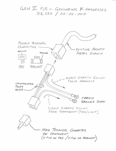
By grounding the headlights to frame he is taking them out of the "chain" and lowering the current threw the S6 spider.
And by grounding the harness end to the frame at each light he is adding 2 more ground wires between the frame and S6 spider.
So after it's done the current going threw the S6 will be lower, the S6 spider will have 2 more wires going to the frame, and one wire (the original) going to frame threw the S4 spider. This should bring the current going threw both spiders way down.
I would prefer this approach because it is lowering the current on the overloaded spiders and the wiring. Instead of fixing the spiders and hoping the wiring is capable. It is dealing with the overload at the source, instead of down steam. And it is done without altering the factory harness.


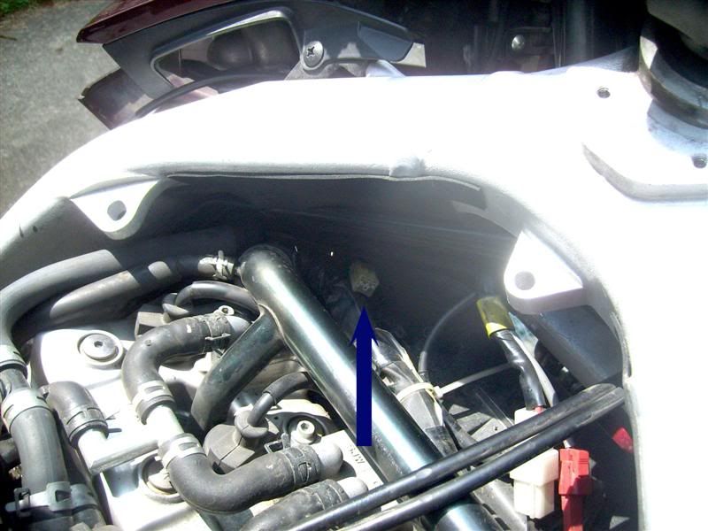
I have the same question. I have spent the past few hours reading up on the S4 problem, then went out and took off a bunch of my plastic. Is this the famous S4 Black Widow (with the cap off and the shiny aluminum spidery thing in it)? There is no way I could get in that tiny area and clip it off and solder or crimp that.Is there a picture of where this thing is at on the bike?
Thanks Art!You got it Marty.
Art
Nope, that'll work. The posi-taps wont have as strong a connection but should be fine. Just make sure you get the right wires or you're in for a surprise.I've been waiting on Yamaha to come up with a fix for this but Canucklehead's failure of 2 spiders this week and a friendly nudge on the topic got me looking into this again.
Plug and play is very nice, and being reversible is all very nice but I'm a cheap bastard. I'm thinking that just PosiTapping into the ground wires of the fans and headlights to provide the additional ground paths would provide the same effect as the RR harnesses and would cost me under $10. Other than the additional labour to install and pinholes in some ground wires if I ever un-install it, does anyone see any other drawbacks of my cheap-ass approach?
My experience is that a properly installed PosiTap, which included using the appropriate size Tap, provides a great connection. Another benefit is this approach elimiates adding 20 crimped connections and 10 spade connections in the connectors (weak points.)Nope, that'll work. The posi-taps wont have as strong a connection but should be fine. Just make sure you get the right wires or you're in for a surprise.
Very good point on the additional connections...My experience is that a properly installed PosiTap, which included using the appropriate size Tap, provides a great connection. Another benefit is this approach elimiates adding 20 crimped connections and 10 spade connections in the connectors (weak points.)Nope, that'll work. The posi-taps wont have as strong a connection but should be fine. Just make sure you get the right wires or you're in for a surprise.
Thanks for the tip! Finding the right wires is pretty easy but I always double check after a tap just to be sure!
Gotta love the technical jargon!... splooge ...
I would have used dielectric... just because conductive grease around electricity gives me the heebies. However, are ALL 6 connections within those spiders ground points? If so then conductive wouldn't be a bad idea at all.Ok, so the way I understand this whole spider thingy is that the connection builds resistance over time because it gets corroded from water and goo getting at the contacts. This resistance creates heat which creates more resistance until it finally melts and leaves you stranded in BF nowhere.
So why don't we just fix the cause and keep the connection from getting corroded? I could just separate the connector, check it for corrosion, fill it with grease, wrap it in electrical tape and put it back together. Problem solved. Maybe if I feel generous I might check it again after 5 years.
Since it's a ground harness would it be better to use a conductive grease or dielectric grease? The dielectric grease might create more resistance if the connectors don't rub hard enough against each other. I think a conductive grease would be better because it would keep the resistance down and the splooge out.