Gerbing's Heat-troller Fix

Yamaha FJR Motorcycle Forum

Help Support Yamaha FJR Motorcycle Forum:

This site may earn a commission from merchant affiliate links, including eBay, Amazon, and others.

Tree Doc

Well-known member
Joined
Apr 19, 2010
Messages
534
Reaction score
17
Location
Arroyo Grande, CA
I think I cooked my single contoller. :glare: I was trouble shooting what turned out to be a bad co-ax plug on a Gerbings extension wire from controller to jacket. While working with my multi-tester, I got a little shaky with the probe and mistakenly crossed polarity. It blew a 15A fuse on my fuseblock which I replaced but now the controller no longer lights it's LED and no power comes through it. If I shake the contoller, I can hear something like a BB rolling around inside.

The housing has a joint where the front is mated to the back half but with a little experimental poking and prodding it doesn't appear that it willingly will come apart to reveal the chewy nougat center that I need to inspect.

Any of you electrical pros have a suggestion to get in or where to go from here?
How old is the controller?

 
When you do open it you'll find all surface mount parts on a little PC board.

You probably toasted the driver FET, (The BB noise you hear might be a piece of the FET's plastic case you blew off with the 15+ amps) it can be replaced if you can solder surface mount parts, although if you reversed the input voltage going into it there might be a fried diode involved.

I have the dual controller and I replaced one FET with a leaded part instead of a surface mount power FET when I toasted it fooling around like you were.

Slipping with test leads generally makes for a bad day, BTDT, many times.

 
Last edited by a moderator:
When you do open it you'll find all surface mount parts on a little PC board.

You probably toasted the driver FET, (The BB noise you hear might be a piece of the FET's plastic case you blew off with the 15+ amps) it can be replaced if you can solder surface mount parts, although if you reversed the input voltage going into it there might be a fried diode involved.

I have the dual controller and I replaced one FET with a leaded part instead of a surface mount power FET when I toasted it fooling around like you were.

Slipping with test leads generally makes for a bad day, BTDT, many times.
Well, I may call on you for pointers if that's OK when I figure out how to gain entry into the housing. I'm far from a circuit board wizard but I can melt solder and I'm very willing to attempt a fix. I can't **** it up anymore than I already have. Well.....maybe I can but I'll have fun trying! :lol:

How old is the controller?
I'd say it's a couple years old. I bought it and the liner second hand and it just predates the newer Microwire jackets.

 
Last edited by a moderator:
Apparently, when Gerbing's found a manufacturer (in China) to produce their first run of heat control units, some of the the first run ones arriving here were having problems. Gerbing's replaced a few of these with a newer "fixed" version at No charge.

Not sure of when exactly, but I think it was in 2004 0r 2005 that these outsourced units first arrived. I think they are fine now, but maybe you got one from that early batch.

just my CO2.

 
I have fixed a number of Heat Trollers. Getting into the case is somewhat destructive, the ones that I have opened have been sealed by means of solvents melting the plastic cover on. Many of the older units were potted with hot-melt glue, I have no idea what they were thinking using that shit. It has been common to find unsoldered pins in the controllers <_< So far I have been able to troubleshoot then find replacements for the defective surface mount components. The most common problem has been FET failures that looks like someone had an OOPS when wiring. Next has been a bias diode that manages B+ then random broken wires and the previously mentioned unsoldered pins. IIRC, the FETs that Warm 'n Safe uses in the Heat Troller are rated for something like 2-3 times more power than their actual use. I have been able to figure out the design of the Troller and understand how it works but will protect their 'intellectual property' and not reveal it in a public forum.

If there was an error in wiring by the installer the deceased component will usually resemble something out of a Kingsford bag and the component value or other identifiers will be illegible. When looking for a replacement FET look for something that can handle at least 10 amps and has a very low RD

 
Last edited by a moderator:
I'm in. I was fooled by what looked like injection molded stems on the back of the housing. Turns out they're screw holes just filled flush with a silicone type sealer. Peeled it out and removed 5 tiny screws, peeled out the silicone potting to allow for slack in the external wires and the circuit board is out.

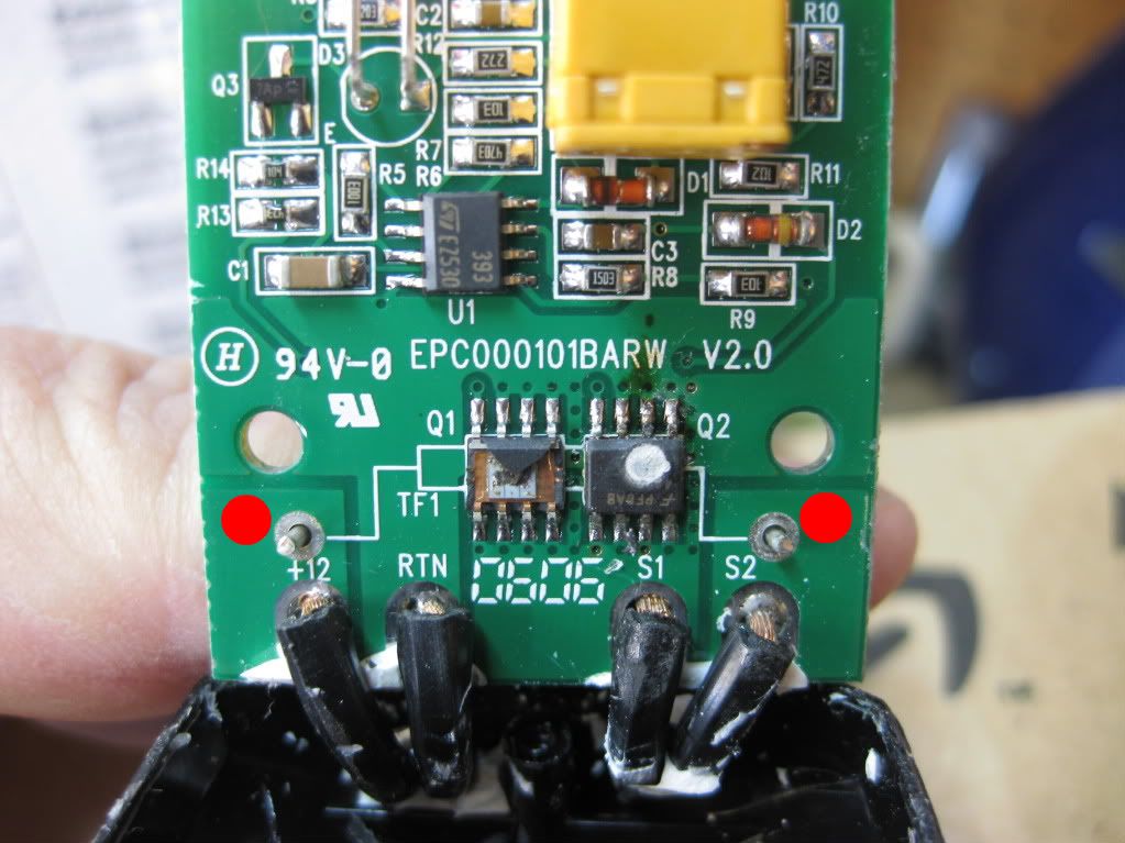
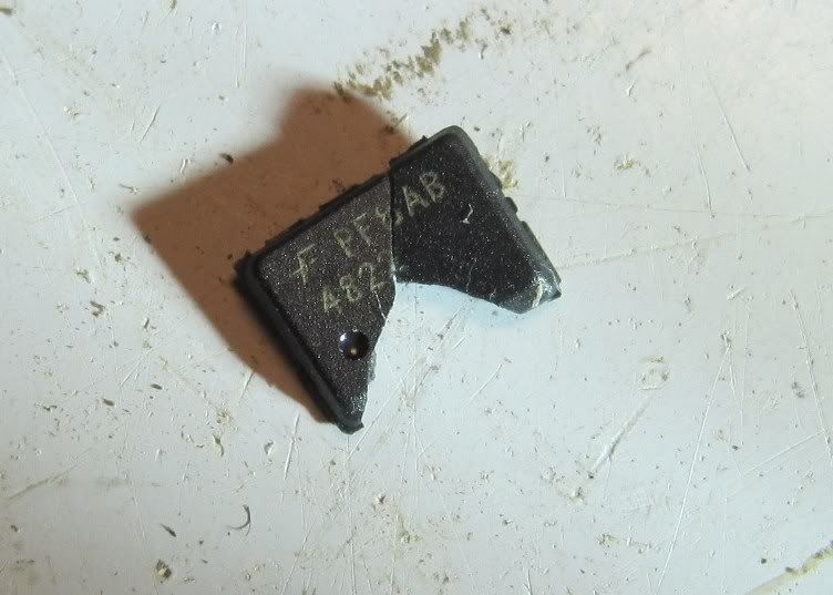
The problem is obvious to my eyes but not so much to my brain. The remnants of the chingadera on the left were the "BB" that was floating around in the housing. Blew that sucker right off. You can see the same was about to happen on the chingadera on the right.

Are these the "FET's" you guys speak of and do you think they were both the same? Is this a Radio Shak item or a more specialized place to find such an animal?

IMG_1874.jpg


Last edited by a moderator:
I'm going with a Fairchild fet, upper most left (pin 4) is the gate, source pins 1-3 & drain 5-8 that's my WAG.

Doubt rat shak's gonna help ya.

Is anything readable on the ejected piece?

I'd be running wires to leaded parts (just cause I already have them as scrap), but I'm a hack.

Allen's input will no doubt be more elegant.

 
Last edited by a moderator:
Gotta love it! Forensics with the Macro on the camera. :yahoo:

Here's what it is....same as the one next to it that started to grenade. PF8AB 4822

I found a JFET at Rat Shak but it was much larger and not spec'd as Ionbeam suggested...nowhere near actually.

FETPieces.jpg


I'm going to Google the bajeezus out this number and see what I can find. Please continue feeding any suggestions you might have. Just the PF8AB got me nowhere before. Would you guys know if this was a MOSFET, JFET, or ? I'm learning by doing, here. Just did a 20 minute Crash Course on FET's from a Physics Phd Prof at a university in India. Dude knows his shit. I think he sold me a squishy down at the Kwiki-Mart last week.

 
Last edited by a moderator:
Wow, TreeDoc, I'm impressed!

But, uh, just wondering if a Warm n' Safe remote controller or wired controller could be placed into service for your gear?

..and, jeesh, doode, you live in the warm part of this county, what up? :huh: :p

 
Wow, TreeDoc, I'm impressed!

But, uh, just wondering if a Warm n' Safe remote controller or wired controller could be placed into service for your gear?

..and, jeesh, doode, you live in the warm part of this county, what up? :huh: :p
Don't be...I'm stupid as shit when it comes to this stuff! :dribble: I'm just dangerous enough to tear into anything, though. Now, if you want to discuss the benefits of Mycorrhizal fungus at the root/soil interface or remove and rig out a 140' Eucalyptus that's 2' away from million dollar house....we'll talk! :lol2:

The wife and I rode the FeeJ up to Salinas last Thursday morning in our full gear w/liners. Freezing fog from Santa Margarita to San Lucas and we were both pretty damned cold. Wife said she wanted heated gear after I told her that "I" had a jacket and gloves sitting at home.

Here we are today with me pokin' my prod in places it shouldn't have been!

You pose a good question, though....

Do I NEED a WnS troller? Is that a better way to go? I just bought this get up and figured I'd salvage it from my mistake but I'm all ears!

 
Last edited by a moderator:
Here's another slightly researched WAG for ya.

https://www.fairchildsemi.com/ds/FD/FDS8672S.pdf (you need the SO-8 style package)

https://www.mouser.com/catalog/catalogUSD/642/507.pdf

Zorlac, You're my new found hero! Thanks for digging up the part and source.

Looking at the data sheet looks promising and I think it'll work.

Do you think you can desolder those two fets without ripping the pads off the board?

:blink: This is my best Deer in Headlights look I can come up with. I don't know, this will be a first. I'd be working with a small pencil type iron but have never attempted something on this tiny scale. Uhhhhh...any pointers?

You really deal 140 footers without property damage on your day job?

Oh yeah. Haven't busted anything more than a sprinkler head in 23 years! ....knock on wood. :lol:
 
Last edited by a moderator:
...

Looking at the data sheet looks promising and I think it'll work.

Do you think you can desolder those two fets without ripping the pads off the board?

:blink: This is my best Deer in Headlights look I can come up with. I don't know, this will be a first. I'd be working with a small pencil type iron but have never attempted something on this tiny scale. Uhhhhh...any pointers?
Get a pair of fine wire cutters, cut each leg of the FET close to the body. Remove the body, you can then sweat each leg off its pad, much less chance of damage than if you try to do the lot at once.
+1and solder wick is your friend if you don't have a solder sucker or nice solder suckie station.

 
Get some solder wick to help remove the pins after they've been cut from the component.

Another thing I've done is to file down the solder point with a file to it's ultra fine.

 
Great pictures Doc!

Zorlac sure seems to have found the correct MOSFET for this application. The pad layout on the PCB matchs the pin layout of the device which further confirms the IC selection. The electrical specs of the FDS8672S are perfect. Notice the dimple on the top of the IC chunk? That is used to denote pin 1 and orients the device on the PCB.

A strong +1 to what mcatrophy suggests about clipping the IC leads near the body then removing the remaining IC legs one at a time, I was going to make that same suggestion.

If Doc can heat the leads and pluck 'em off one at a time I would do that and avoid using solder wick in this situation. The solder wick will cause too much heat to be concentrated on the tiny pads.

Quality solder iron tips are plated so that solder will 'wet' the tip, sanding or filing the tip takes off the plating. You are usually better off buying the correct tip if possible.

 
Last edited by a moderator:
Great suggestions and thanks Ion for that dimple info for orientation. I was wondering how to determine that.

I ordered my FET's. Good thing I got my order in when I did. They're down to about 8000 pieces left in stock before I got the 4. I bought a couple extra for when I test the wiring again! :lol2:

 
Top