Dave_bris
Member
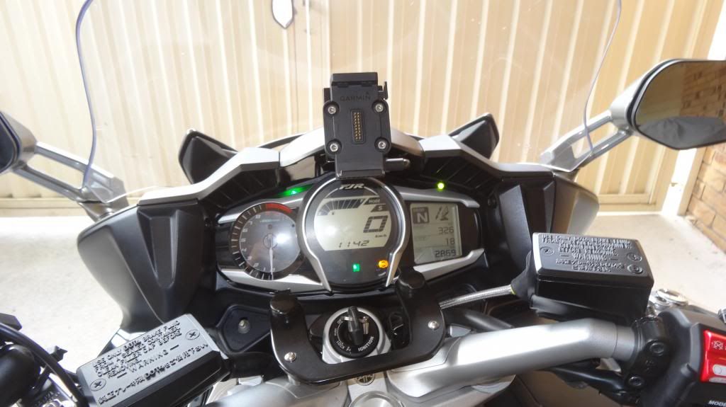
Here are some pictures of the mount I had made up for my Zumo 660.
I wanted to have the GPS in my field of view when looking at the road rather than down between the handlebars where I had it on my Gen 2.
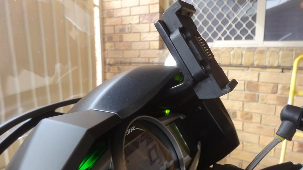
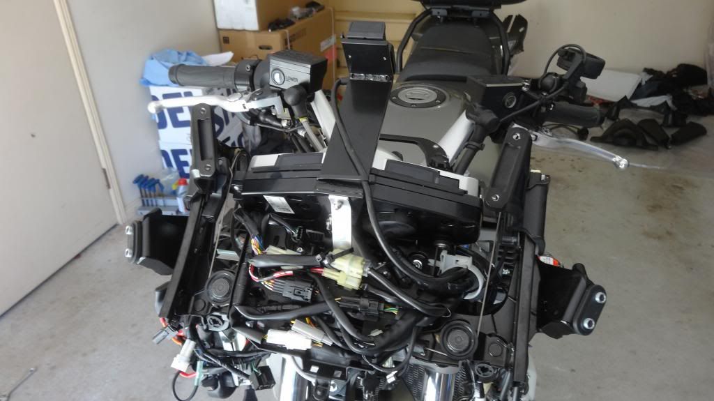
The GPS bracket attaches to the cast aluminium plate behind the speedo. Initially I had a problem with the unit vibrating so I had to add the silver aluminium supporting bracket you can see in the last photo. Now it is completely stable.
The standard Zumo fitting attaches to the bracket by 4 allen head screws into 4 tapped M4 holes in the aluminium bracket.
The bracket is made from 6mm aluminium and then powdercoated. The three pieces were cut out on a CNC milling machine and then welded but that is right outside my area of knowledge.
The bracket is largely out of sight as it sits in the large air channel above the instruments.
Please don't ask me to supply the bracket as I had to go to a fabricator (here in Brisbane, Australia) to have it made up. It cost me $150 for this and another small bracket to be made up but it did take many hours to remove all the fairings and nose piece to get access behind the instruments. I do have drawings for the bracket if anyone wants to get one made up.
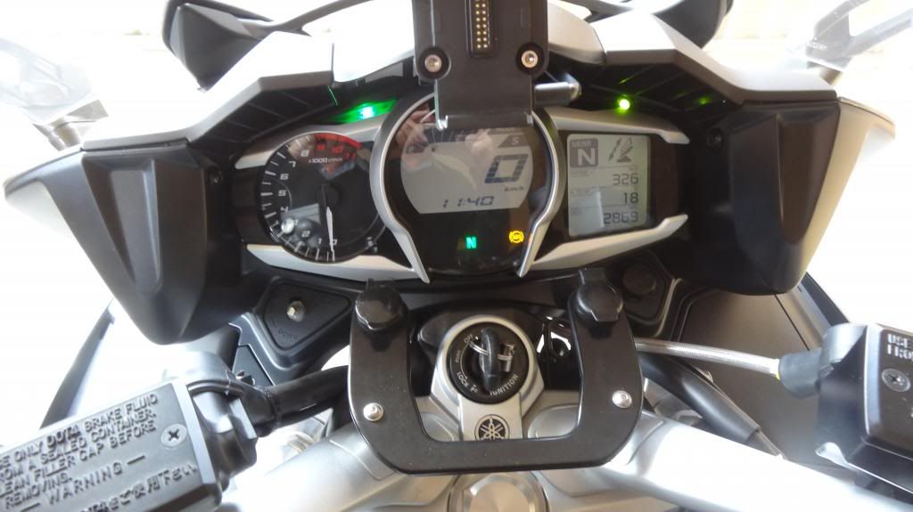
When I sit on the bike the bottom of the GPS lines up with the bottom of the FJR logo above the speedo. The only negative is that the GPS blocks my sight to the green flasher lights.
The green LED you can see to the right of the GPS is a Clearwater Voltage Sentry.
Dave
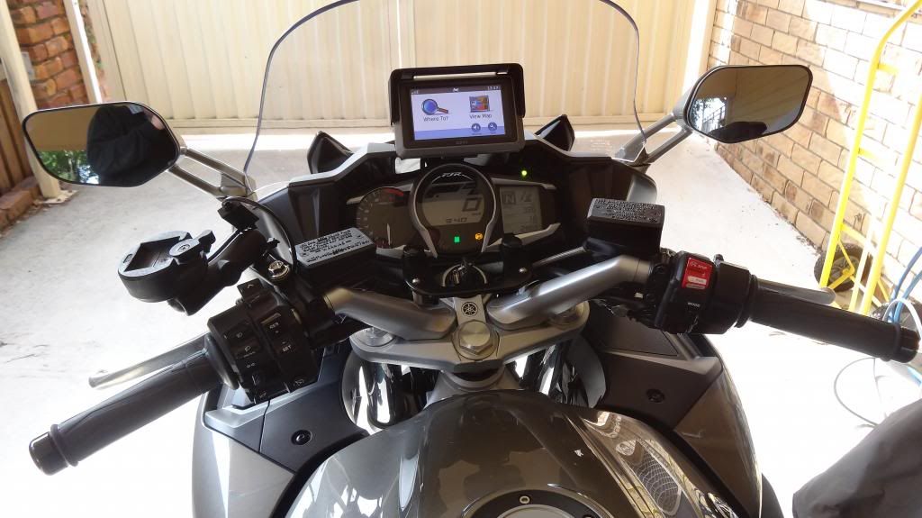
I wanted to have the GPS in my field of view when looking at the road rather than down between the handlebars where I had it on my Gen 2.
The GPS bracket attaches to the cast aluminium plate behind the speedo. Initially I had a problem with the unit vibrating so I had to add the silver aluminium supporting bracket you can see in the last photo. Now it is completely stable.
The standard Zumo fitting attaches to the bracket by 4 allen head screws into 4 tapped M4 holes in the aluminium bracket.
The bracket is made from 6mm aluminium and then powdercoated. The three pieces were cut out on a CNC milling machine and then welded but that is right outside my area of knowledge.
The bracket is largely out of sight as it sits in the large air channel above the instruments.
Please don't ask me to supply the bracket as I had to go to a fabricator (here in Brisbane, Australia) to have it made up. It cost me $150 for this and another small bracket to be made up but it did take many hours to remove all the fairings and nose piece to get access behind the instruments. I do have drawings for the bracket if anyone wants to get one made up.
When I sit on the bike the bottom of the GPS lines up with the bottom of the FJR logo above the speedo. The only negative is that the GPS blocks my sight to the green flasher lights.
The green LED you can see to the right of the GPS is a Clearwater Voltage Sentry.
Dave