GunMD
Well-known member
After searching for photos of locations where folks have installed Heat-Trollers, I decided to put mine just to the left of the "A" panel. I chose this location because it seems like it will be a convinient place to reach the adjustment knobs and there was a TON of room under the panel.
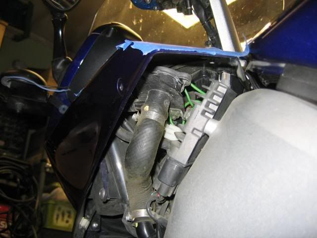
First, I removed the left side fairing. As you can see from this pic, there is plenty of room for the Heat-troller's adjustment knobs and LEDs.
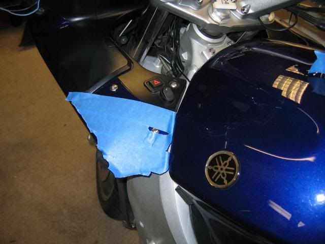
Next, I masked off the area where I was going to be working in order to 1) prevent scratches, and 2) provide a surface conducive to marking the location of the holes that I would be drilling later.
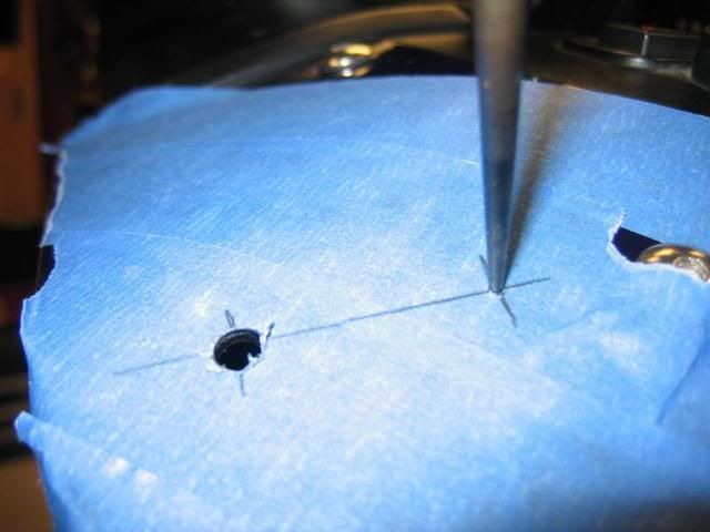
Once I decided where I wanted the adjustment knobs to be located I marked the tape with a pencil and used an awl to mark the spot of the first hole to be drilled. Once I had the first hole drilled (and made sure it was actually where I intended it to be) with a 1/4" drill bit I marked the location of the second hole with the awl.
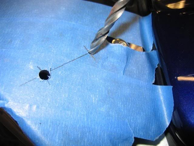
Once I had both holes drilled I marked the location of the two smaller holes ( 1/8" drill bit) for the LEDs. I then drilled the two holes for the LEDs.
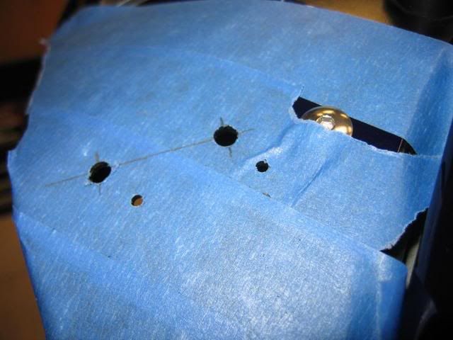
Once I had all four holes drilled I removed the masking tape.
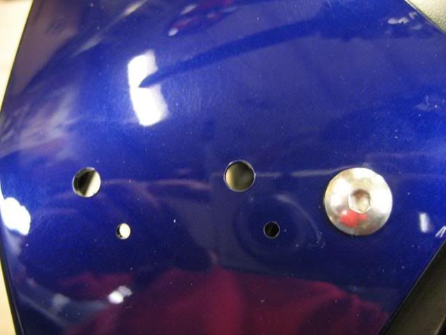
After routing the wiring from the Heat-Troller to the location of the adjustment knobs I installed the two switches and two LEDs. In order to get the posts of the adjustment switches through the 1/4" holes I had to break out the drill again and enlarge the holes slightly. While this added an extra step to the process I was more than happy that the hole was a bit snug, rather than being too large. Once a hole gets too larger there's really no going back. After making the holes a bit larger I was able to insert the two posts and the two LEDs into the holes from the underside of the fairing. I then reinstalled the washer, nut, and O-ring on each post before finally placing the adjustment knobs onto the posts and securing them with set screws.
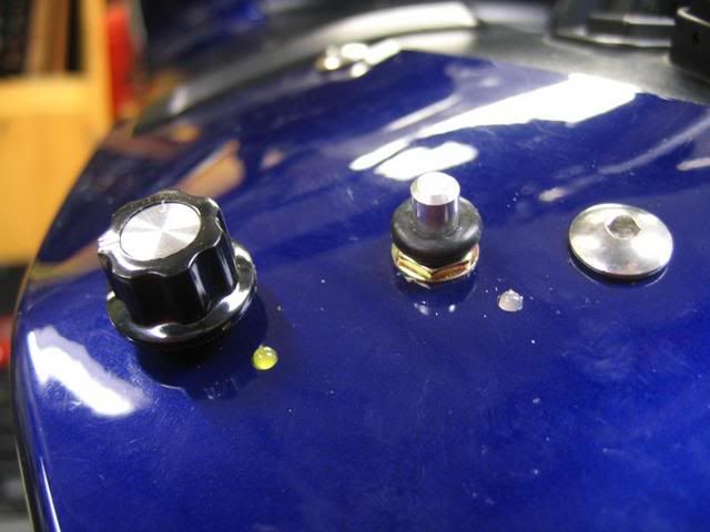
Here you can see the switches installed from under the fairing's top panel.
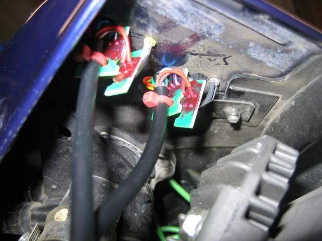
Tomorrow I'll secure the LEDs with some silicone and put the plastic back in place. I'll be warm 'n' toasty as soon as my heated jacket liner arrives.
First, I removed the left side fairing. As you can see from this pic, there is plenty of room for the Heat-troller's adjustment knobs and LEDs.

Next, I masked off the area where I was going to be working in order to 1) prevent scratches, and 2) provide a surface conducive to marking the location of the holes that I would be drilling later.

Once I decided where I wanted the adjustment knobs to be located I marked the tape with a pencil and used an awl to mark the spot of the first hole to be drilled. Once I had the first hole drilled (and made sure it was actually where I intended it to be) with a 1/4" drill bit I marked the location of the second hole with the awl.


Once I had both holes drilled I marked the location of the two smaller holes ( 1/8" drill bit) for the LEDs. I then drilled the two holes for the LEDs.

Once I had all four holes drilled I removed the masking tape.

After routing the wiring from the Heat-Troller to the location of the adjustment knobs I installed the two switches and two LEDs. In order to get the posts of the adjustment switches through the 1/4" holes I had to break out the drill again and enlarge the holes slightly. While this added an extra step to the process I was more than happy that the hole was a bit snug, rather than being too large. Once a hole gets too larger there's really no going back. After making the holes a bit larger I was able to insert the two posts and the two LEDs into the holes from the underside of the fairing. I then reinstalled the washer, nut, and O-ring on each post before finally placing the adjustment knobs onto the posts and securing them with set screws.

Here you can see the switches installed from under the fairing's top panel.

Tomorrow I'll secure the LEDs with some silicone and put the plastic back in place. I'll be warm 'n' toasty as soon as my heated jacket liner arrives.


