New Owner - Need Electrical Advice

Yamaha FJR Motorcycle Forum

Help Support Yamaha FJR Motorcycle Forum:

This site may earn a commission from merchant affiliate links, including eBay, Amazon, and others.
I passed on the Hyperlites and went with AdMore bar.

If you decide to go with PDM60, you can set any channel to power ON/OFF with switch to GROUND (this is seperate, or optionally in conjunction with, ignition sense) giving you that "keep alive" setting you want

Example

1 - ALWAYS ON (not recommended due to parasite draw)

2 - IGNITION Sense

3 - GROUND Sense

4 - BOTH Ignition AND Ground Sense

5 - EITHER Ignition AND Ground Sense

6 - INACTIVE

 
1. If you turn off your ignition, then everything goes off, including anything that's "switched" on the fuzeblock. Anything "unswitched" from the fuzeblock stays on. You can pull the key out to refuel, whatever.2. Turning off the additional switch I suggest then turns off anything remaining in the fuzeblock. Such a switch could be replaced/augmented by a time-delay-off relay.

What am I missing, other than the limit on the number of circuits a fuzeblock can handle?
Nothing ... That is a logical solution and you thought it out better than I did ... which is why I asked in the first place
biggrin.png


It would require a switch able to handle the full capacity of thr Fuzeblock, but it's suddenly become my preferred solution!

Edit ... or a relay :)

 
Last edited by a moderator:
Twigg

Just to throw more mud in the pool...

The Fuze Block FZ-1 is a really nice set up with an on board relay. All 6 circuits give you the option of either switched by the relay, or un switched depending on how you insert the mini fuses. It limits you to 10 amps max per circuit - AND 30 amps total for all 6 circuits. See their website for more information.

The Eastern Beaver PC8 has no relay on board, you supply your own. Two branches are available on its board - one branch has 2 circuits, the other branch has 6 circuits. Typically the 2 circuit branch is wired always on. This fuse panel has a much higher amperage rating both per circuit. See their website for more information.

Both are nice tight compact fuse panels that are more densely built than your Blue Sea fuse panel. If space saving is your goal, either of these two units will help you achieve it. At one time I ran both on my '06, one switched with by my running lights (key on), the other switched by my headlight (engine running). Currently I am running the Eastern Beaver unit switched by my headlight.

If I had a clean slate again, the Rowe Electronics PDM60 electronic power module would be the way to go. It's smaller than these fuse panels, water proof, programmable for all 6 circuits and (needing no access) can be placed under the dash panels out of sight. If you have the coin that would be one sweet set up. If you needed more circuits, who's to say that you couldn't use 2 of its circuits to power another fuse sub panel.

Whatever you build make sure it is bullet proof. Keep it separate from the OEM Yamaha wiring - including the black ground wires. Size your wires big and keep the wire lengths short for minimal voltage drop. Get a good voltage monitor like a Datel (xx.x) and hook it up across the battery terminals along with your battery tender fused lead. And stay away from the SHORAI battery, it's standing voltage (charging threshold) is .5 volts higher than the standard led acid battery that came with the bike.

When out on the road after several long days, electrical problems are the last thing you need to deal with.

Have fun with your new bike. The mighty V4 Venture was a great machine (I should know, mine was a 1990 blue on blue), but it's day has come and gone. Welcome to the modern world.

Brodie
rolleyes.gif


Last edited by a moderator:
By the way, if you are looking for a good high amp capacity automotive relay...

You can get a 70 amp rated automotive relay with matching socket for around $12 at www.onlinecomponents.com. When I was building my ignition relay harnesses before Yamaha came out with the ignition switch recall, this is the relay I chose. It's cheap enough to get 2 of them,and get 2 sockets - they are handy things. Use the socket. Should you need to replace the relay, having it socketed makes it a no brainer.

70 amp relay

Panasonic CB1Ah-12V

Relay socket kit

NTE R95-160A

Brodie
rolleyes.gif


Last edited by a moderator:
Brodie summed it up quite well! All great info and adviceI

I personally look forward to never having to change a fuse!

 
I agree, Brodie summed it up beautifully :)

I would probably choose the PDM60, but the cost is high, besides, I am very happy for any profit to go to Curt Gran's wife. So there is a Fuzeblock and a relay (with socket and thick wires) in my future.

All I need to do now is seek out those posts where folk have devised a two-switch bracket for the handlebars. One switch for the relay and another to isolate the LR5 LEDs. They will be triggered by the High Beams, but I want a way to isolate them too.

Thanks guys.

 
I was intrigued by the PDM60 until I discovered that to program it requires a Windoze environment. Not going back there.

In any case, I've farkled all the electric stuff on the FJR I'm going to and only have 2 very low amperage things I need to deal with, so I'm going with just a relay and harness: 6 bucks total plus shipping.

 
Last edited by a moderator:
While you are getting all electrofarkeled, keep in mind the Gen I stator only puts our 490 watts @ 5k rpm, less watts at less rpm. You have roughly 100 watts to play with.
Actually, my calculations come to about 200 watts to play with; when you don't factor in the fans. The fan is a manageable draw. If your fans are running, you most likely don't need your heated gear turned up, or your aux lights on. I run about 110 watts of aux lighting on the Gen1, and it does fine with my heated liner and gloves on full power as well.

 
Actually, my calculations come to about 200 watts to play with; when you don't factor in the fans. The fan is a manageable draw. If your fans are running, you most likely don't need your heated gear turned up, or your aux lights on. I run about 110 watts of aux lighting on the Gen1, and it does fine with my heated liner and gloves on full power as well.
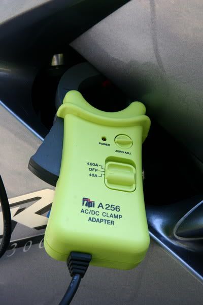
I arrived at my suggested wattage head-room by using my clamp-on amp probe

IMG_8551sm.jpg


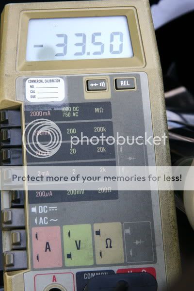
to measure the current flowing from the R/R to the battery with everything on including my heated grips, and 30% aux lighting

MaxAmps.jpg


With nothing on but the normal lighting and low beams I measured 27 amps = 378 watts @ 14 VDC.

Running a pair of 2,000 Lumen ea LED floods with my heated grips on high, with the engine turning between 3k & 4k rpm they take my battery voltage down fairly low, then if my wife turns on her electric coat liner we can run the voltage down to what I consider too low and we start a trade off game. Because I do have some excess voltage drop in my system I monitor the R/R current to get a picture of how hard my stator is working. When I see 470 to 480 watts being tapped from a 490 watt 5k rpm system I have a concern.

I don't know why my functioning, non problem FJR draws so much more basic system current than yours does. If you are suggesting that everyone's Gen I has ~200 watts to play with you may want to also recommend a volt meter and some voltage guide lines. I'm envious of your surplus power! :)

 
Last edited by a moderator:
Actually, my calculations come to about 200 watts to play with; when you don't factor in the fans. The fan is a manageable draw. If your fans are running, you most likely don't need your heated gear turned up, or your aux lights on. I run about 110 watts of aux lighting on the Gen1, and it does fine with my heated liner and gloves on full power as well.
I arrived at my suggested wattage head-room by using my clamp-on amp probe

SNIP

I don't know why my functioning, non problem FJR draws so much more basic system current than yours does. If you are suggesting that everyone's Gen I has ~200 watts to play with you may want to also recommend a volt meter and some voltage guide lines. I'm envious of your surplus power!
smile.png
I didn't mean to call your calculations into question. I thought you were including the fans as well. If you were, then they are pretty much spot on. I can run 100+ watts of aux lighting, heating liner (77 watts), heated gloves (21 watts) 2 GPS and a radar detector (3-5 watts top), for hours on end, and my voltmeter does not drop below 13.5.

I'm suggesting that with the fans not running, a Gen1 FJR should have close to 200 watts to play with. Soon as my fans turn on, system voltage drops like a rock. And yes, when RPMs drop, and stator output drops, I manage that by turning things down as well.

And yes, everyone should run a voltmeter on their bike
smile.png


Last edited by a moderator:
At the risk of thread drift I bring this subject up.

... Because I do have some excess voltage drop in my system ...

You may want to look into doing what Don Carver worked out - running an 8 gage, two wire, fused branch directly between the voltage regulator and your battery. Because our bikes are aging, the electrical wiring is subject to increasing resistance in every connector. This direct run will give your battery the best possible chance to stay charged while heavy draws are placed upon it.

Watching my Datel, before I did this modification the voltage dropped considerably when both my Heat Trollers and my Clearwater Lights Glendas (4) and Kristas (2) we're turned on. Just that extra load turned up to full draw took my Datel (hooked directly to batt + and - terminals) into 12.9 volt territory. I've got an '06 second Gen. bike with the added AE overhead. I've watched the electrical system deteriorate through the years to that point. After the modification it drops down to 13.7 volts with the same load. My slow cooker drops it down another .3 volts.

I'm convinced that the mod helps these aging bikes.

Brodie

:)

 
Last edited by a moderator:
At the risk of thread drift I bring this subject up.

You may want to look into doing what Don Carver worked out - running an 8 gage, two wire, fused branch directly between the voltage regulator and your battery. Because our bikes are aging, the electrical wiring is subject to increasing resistance in every connector. This direct run will give your battery the best possible chance to stay charged while heavy draws are placed upon it.

I'm convinced that the mod helps these aging bikes.

Brodie

:)
Is there a fuller description of this mod?

 
Check out https://roadstercycle.com/ He makes a custom fused wiring harness for our FJR's that bypasses the circuitous route the stock harness takes from the RR and takes it straight to the battery. Harness is made with correct plug for the RR, an inline circuit breaker and terminals for the battery. When running my LR4's, Mondo Moto 100's, highbeam, heated grips on high, phone and gps my relay controlled Datel voltmeter shows 14v at 2000 rpm . I highly recommend this mod, whether DIY or using Jack's harness. Price is about $45.

 
Check out https://roadstercycle.com/ He makes a custom fused wiring harness for our FJR's that bypasses the circuitous route the stock harness takes from the RR and takes it straight to the battery. Harness is made with correct plug for the RR, an inline circuit breaker and terminals for the battery. When running my LR4's, Mondo Moto 100's, highbeam, heated grips on high, phone and gps my relay controlled Datel voltmeter shows 14v at 2000 rpm . I highly recommend this mod, whether DIY or using Jack's harness. Price is about $45.
Thanks ... That looks like a no-brainer, and a reasonable cost.

 
Don't worry.....it won't be ABS too much longer....
lol.gif
Really?...What goes wrong? Now you have me worrying about something I didn't think I would have in the first place
That's what we're here for
laugh.png


On the Gen I it is the hydraulic pressure control block that freezes up (ever so rarely). It is unrepairable, replace only. For $$$$$$$$$$.$$. Or, you continue to ride with no problems other than no rear ABS. So far there is no documented front ABS failure.
Let me change that then...

On the '04 ABS that I was messing with last week, both the front and the rear were frozen up, though the rear was worse than the front. On both ends I could not turn the wheel by hand at all when exercising the ABS using the test jumper and diagnostic procedure. The front wheel at least vibrated a little, the back wheel was a dead fish.

When you think about it, riders often get into the ABS on the rear wheel. All it takes is a heavy downshift with the brakes on and the back ABS starts pulsing. But it is seldom that you get to feel the front ABS cycle unless you are intentionally doing it. I guess that is something to think about right before you grab a big hand-full of front brake expecting it to modulate...

 
Last edited by a moderator:
To the OPs question:

I've found it is handy on these bikes to have two separate power panels: One small one up in the nose faring to power electronic doo-dads and heated grips and a second one underneath the seat is required for heated gear. My front one is relay switched with the ignition, the rear one is fused but unswitched for simplicity, though it could also be relayed and switched if you wanted to.

You will have a tough time finding space anywhere in the front for anything as large as a BlueSea panel. With a FuzeBlock you'll have a chance. I just made mine myself from a terminal strip.

I don't really see the need to have the accessories turn off and on with a handlebar switch as long as they all go off when the bike does. Generally you will want to turn the individual items on or off as needed, or to conserve watts when you are using a lot of heated gear.

+1 on the Datel recco.

 
Last edited by a moderator:
Because most of my gadgets are up front I put my power distribution up front. I have two terminal strips, one attached to the left front sub frame (at the bottom of the dash) that is relay switched and one on the right that is always +12 volts. I use the terminal strips for both power and ground. To come off the battery I use power taps similar to this:

31dbznrZJrL.jpg


The tap goes under the battery bolt and allows the use of 3/4 spade connectors. I used a 4 position tap but on the FJR I had to bend the taps down to get space for the mating spade connectors to fit under the plastic.

 
To the OPs question:

I don't really see the need to have the accessories turn off and on with a handlebar switch as long as they all go off when the bike does. Generally you will want to turn the individual items on or off as needed, or to conserve watts when you are using a lot of heated gear.

+1 on the Datel recco.
I am not new to LD Riding. I have been doing this a few years, and when I set up my Venture I made all the mistakes folk regularly make, then I found a few of my own, and made them too! By the time I sold the Venture, it was set up to rally about as well as it could be, for me. I know how I want my accessories to behave and I'm looking for ways to make it happen.

The 2005 FJR I have has already done 88000 miles, and managed that with an almost unscathed wiring loom. My Venture, even though it worked well had its wiring hacked around by several previous owners, and by me. That is not going to happen again. This time I will get it right.

So .... I have a need for my "up-front" stuff .... Radio, GPS (2) and charging ports to NOT go off with the key, until I decide to turn them off. The Venture had an ACC position on the key, the FJR does not and if I simply kill the engine with the Kill Switch, the headlight stays on. What I want is to be able to shut the bike down but keep those items running until I turn them off ... and I want that easy with one step, not multiple.

I learned a long time ago that one key to successful LD Riding is preparation, and reducing what you have to do, and to remember, to an absolute minimum because the more steps you need to take, the higher are the chances you will forget one of them. So yes, I want my accessories to remain on, and go off with a single switch.

The solution is straightforward, and was detailed in a helpful reply above.

I have ordered a Fuzeblock. The main feed to the Fuzeblock will be controlled by a relay, and that relay will have a switch to activate it on the handlebars, or close by. All the accessories I want to remain ON will be "always on" in the Fuzeblock. Anything else (LED lights, Heated Grips) will be "switched" in the FB. The switch will then shut off power to everything that is "always on". It's very simple, and a neat solution.

Apart from pozi-taps for triggers, that also leaves the original wiring untouched ... bonus.

My decision now is where to mount the Fuzeblock. That is a little dependent on the Cruise Control I end up with. I could use either the tool try or the space under the rear seat, but I'm not sure which would be better in terms of leaving sufficient space for the CC.


Latest posts

Top