Reparing Your Ignition Switch

Yamaha FJR Motorcycle Forum

Help Support Yamaha FJR Motorcycle Forum:

This site may earn a commission from merchant affiliate links, including eBay, Amazon, and others.
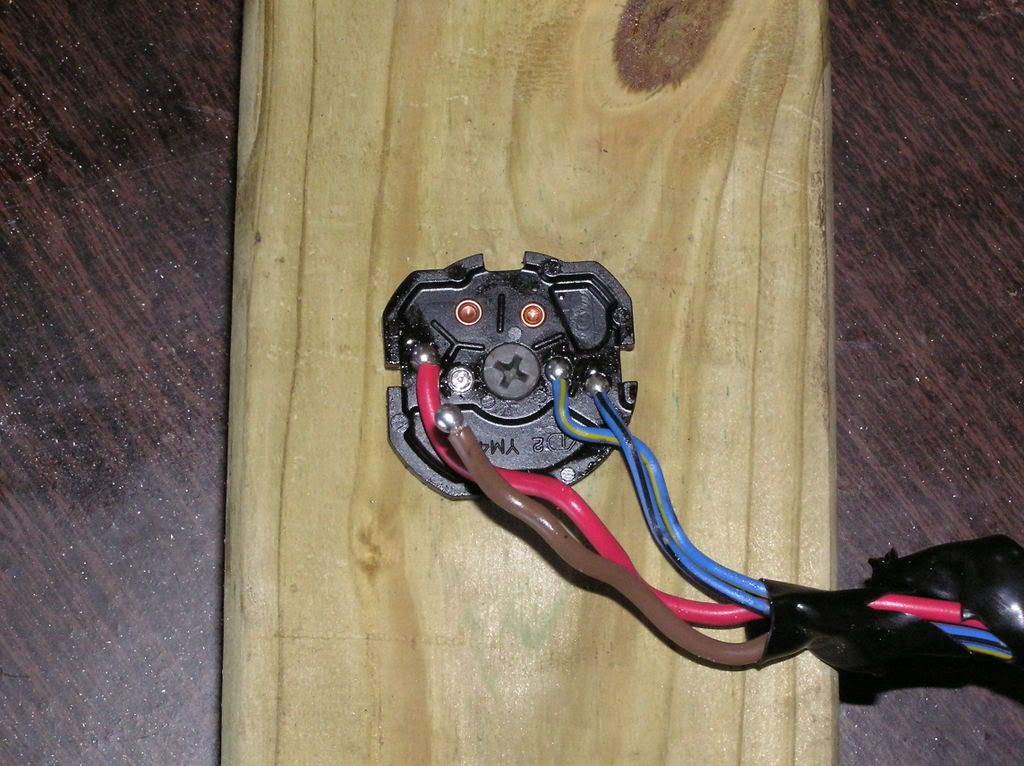
I would definately aggree the cold solder is the correct diagnosis. While performing the repair I noticed the plastic surrounding the copper terminal would start to melt when I held the soldering iron on it to pre-heat the terminal. This tells me that durring the manufacturing the joint couldn't possibly be done right.
...And not an overheating of the terminal if the surrounding plastic was intact ! ;)

 
I agree with others, kudos on the documentation! I have one other ignition switch mod "to add" however. If any one digs their switch out again, take the copper contacts out an have them gold plated! It's not expensive to have done, and it will keep the contacts from corroding, especially if a bike is left out in the wet very often.

The "pejorative" of metal smiths (jewelry metal casters) goes like this;

Goldsmiths never tarnish

Silversmiths tarnish only slightly,

while Coppersmiths turn green with envy!

Note; when copper tarnishes (oxidizes) it turns green!

 
I would definately aggree the cold solder is the correct diagnosis. While performing the repair I noticed the plastic surrounding the copper terminal would start to melt when I held the soldering iron on it to pre-heat the terminal. This tells me that durring the manufacturing the joint couldn't possibly be done right.
...And not an overheating of the terminal if the surrounding plastic was intact ! ;)
Exactly because if the terminal had been super-heated it would show evidence of that

 
Last edited by a moderator:
The contacts in the ignition switch have a very large body mass for conventional soldering, the mass wicks heat away making them hard to solder. High volume manufacturers will often use an impulse welder to make the wire to terminal connection. In the picture below, copied from DailyCommuter, you will see two unsoldered copper terminals which appear tiny on this side of the switch, but when the switch is turned over you can see the bigger contacts. (World Immobilizer circuit contacts I believe.) The contact from which the wire has popped off is shiny with no signs of fracture, the solder ball remains on the wire and it is shiny and shows no signs of fracturing. Having some experience in setting up and programming impulse welders I would venture that the switch manufacturer had a manufacturing process problem resulting in not getting full fusion between the copper dot and the wire. Even though an impulse weld looks like it is nearly instant, there are usually 5 or more thermal profile steps taking place. Lots of room for error. Also, the switch manufacturer may have several impulse welders and perhaps only one had a problem, or perhaps the process in on the edge, resulting in some good and some bad connections.

The reason there is no heat distortion of the plastic part is because the impulse weld is so quick and so specific to the area that there is no time for plastic deformation. A solder iron has to add lots and lots of heat to the mass of the contact before the solder will flow. As mentioned earlier, solder joints are just for conductivity, not mechanical strength.

Picture007.jpg


Last edited by a moderator:
Chris

Helluva good write-up and pics, thank you for sharing. And thank you Ionbeam for your explanation of impulse welding.

Till now I was more familiar with "impulse wedding" and its catastrophic consequences... :rolleyes:

(j/k: I truly appreciate your crystal clear analysis of the problem.)

Stef

 
Last edited by a moderator:
...Almost all of the 590 watts the Gen II can produce must flow through the ignition switch. Just for shits type numbers -- lets say that the switch has 1 ohm...
I know it's not Friday, but purely for accuracy, most of the current doesn't go through the switch, the high load stuff is all switched through relays.

Also, I would say a 1 ohm contact resistance for this type of switch would be totally unacceptable. I would expect nearer 0.05 ohms. Just my .02's worth.

 
mcatrophy Posted Apr 28 2008, 06:52 PM

for accuracy, most of the current doesn't go through the switch, the high load stuff is all switched through relays.

Also, I would say a 1 ohm contact resistance for this type of switch would be totally unacceptable. I would expect nearer 0.05 ohms. Just my .02's worth
I agree with what you are saying mcatrophy. However, a quick perusal through the FSM will show that the electrical load goes from battery through the main fuse to the ignition switch and then on to the fuse block. No relay.

Edit: upon further review, several main power consumers DO go through a relay, but after passing through the ignition switch, with the exception of the radiator fan.

If I were a designer for the primary electrical system I would expect 0.05 ohms to be an acceptable resistance drop. Upon actual measurement of my electrical system it ain't happening. Based on the electrical readings from other FJR threads it looks like the actual voltage drop for most systems is in the range of 0.75 to 1.0 ohms.

Need data. Input!

 
Last edited by a moderator:
The contacts in the ignition .......blah.........blah...........blah............
You are a frigging electrical geek!!!!

And we all thank your very much for that.

Jeese, I mean I really hate it when I learn something new - that means something I already knew just got forcibly squeezed out of my finite capacity melon. :p

 
mcatrophy Posted Apr 28 2008, 06:52 PM

for accuracy, most of the current doesn't go through the switch, the high load stuff is all switched through relays.
I agree with what you are saying mcatrophy. However, a quick perusal through the FSM will show that the electrical load goes from battery through the main fuse to the ignition switch and then on to the fuse block. No relay.

Edit: upon further review, several main power consumers DO go through a relay, but after passing through the ignition switch, with the exception of the radiator fan.

If I were a designer for the primary electrical system I would expect 0.05 ohms to be an acceptable resistance drop. Upon actual measurement of my electrical system it ain't happening. Based on the electrical readings from other FJR threads it looks like the actual voltage drop for most systems is in the range of 0.75 to 1.0 ohms.

Need data. Input!
Yes, you are quite right, my humble apologies. Just had a closer look myself. I was thinking back to my previous bike, where all the main loads were through relays from the battery/alternator bus. There's only the fans and the ABS that bypass the switch. (Does that mean the ABS works with the ignition off? Does it draw current when the bike is parked up?)

Slight confusion though, you say a drop of .75 to 1 ohm. Do you mean .75 to 1 volt? (As an electronics engineer, albeit semi-retired, I worry about the semantics :unsure: )

 
it looks like the actual voltage drop for most systems is in the range of 0.75 to 1.0 ohms.
it looks like the actual voltage drop for most systems [SIZE=12pt]results from resistance [/SIZE]in the range of 0.75 to 1.0 ohms :blushing:

(As an electronics engineer, albeit semi-retired, I worry about the semantics )
That wasn't semantics, that was a clear cut FU on my part, in spite of all the words I didn't manage say what I meant. Proof reading is good thing, and I didn't proof read this. Thanks for pointing it out! (Hope I got it right this time!)

 
Last edited by a moderator:
and here it is.... the fix.. My bike is down, this is the problem... and here is the fix.... Once again the forum save the frikken day.... Y'all rock.. I am gonna do this tomarrow and as my 8 day ride starts on Sunday

Niiiiiiiiiiiiiiceee

 
Just for reference 4mm x 10mm is the correct size.. and I spent a whopping 43 cents on them..... it was also a fine time to do a TBSync

My bike is cooling dow.. she got pretty hot RUNNING << Thank you very much << during the sync.. Then I will put her the rest of the way back together... She is a happy girl and I am going to buy her a present tomorrow....

 
My ignition switch died on a windy road in Montana Sunday night.

Pushed the bike about half a mile to find a place slightly out of the wind. Used my extra headlight bulb & some wires to make sure that I had power all the way to the switch. Of course I did so .. [remembering what I read on this forum] I cut the wires to the switch and wired the big to big & little to little. Ignition, awesome! Monday, found a switch [3 way was all I could find] and wired the big wires to it. Left the little wires hooked together. Cut up a plastic butter cup lid to fit the switch, put a hole in the middle & two slits on the sides for a tie strap. Put it on the closest bolt. Ran like that for another 1500 miles.

Now, as Paul Harvey says, the rest of the story. Part is order, on back order until a release date of June 30th which means that I should have it by July 8th. Would you believe that Yamaha has no way to tell if a dealer has one in stock? What a large crook of shit ..... and they had to have the bike before they would order the switch.

What's worse, even with all of that, I love this bike! :yahoo:

 
Awesome write up! I just wanted to add my own recent experience, I was sitting at a gas station in Kanab, Utah and the ignition went completely dead. I called the guys in prosser, wa, and they gave me the lowdown on what wires I needed to connect.

Basically, i lifted the tank, disconnected the ignition switch wiring harness, and created two different wiring harnesses (with toggle switches). One was for power and the other for the sensors. This was a quick fix and I was able to get the materials at a hardware shop across the street. Also, did not need to cut, splice or alter any of the original wiring. Ran it like that for the 1000+ miles home.

Hope this helps,

Davy

 
Here is a picture of the security bolts that Yamaha uses to secure the ignition housing to the triple tree.

You can use a standard bolt instead of these.

100_2180.JPG


Last edited by a moderator:
Thanks to all for the valuable info I found here. It looks like my 2003 FJR ignition is on the way out; it did not want to light things up after I shut it off in a traffic jam to let thing cool down. After spraying some WD40 in the key slot and playing with the switch (turning it off and on, turning it halfway) I managed to get it home, which was only twenty miles. Looks like I may be removing the switch for a closer inspection. Many thanks to the guy that posted the pictures and to all describing their experiences> I probably should visit this site more often, but that would take time away from riding! Except for a bad battery a couple years ago, the bike has been mostly trouble-free.

 
Top