The Recall Ignition Switch - What's new about it?

Yamaha FJR Motorcycle Forum

Help Support Yamaha FJR Motorcycle Forum:

This site may earn a commission from merchant affiliate links, including eBay, Amazon, and others.
I'll chime in, thanks Brodie! Once again you have helped. Your efforts do not go un-noticed as evidenced here on the board. And hopefully with your fine harness set-up and the new ignition-fix, we can put the ignition switch problem to rest once and for all. Thanks again. PM. <>< ;)

 
I guess I need to re phrase my post then

Dude-

nice work :clapping: :yahoo:

pardon the internet faux paux

again-

nice work

So-just to get this straight-

you had the recall work done, then disassembled the ignition for enlightenment and documentation. :blink: :blink: :blink:

Analysed the differences and posted them :dribble: :dribble: :dribble:

:love:

I"m feeling warm and fuzy

:wub:
Hey ****

I hate to break it to you,

I know it's going to crush you...
 

You're not my type!


Sorry

:p
 
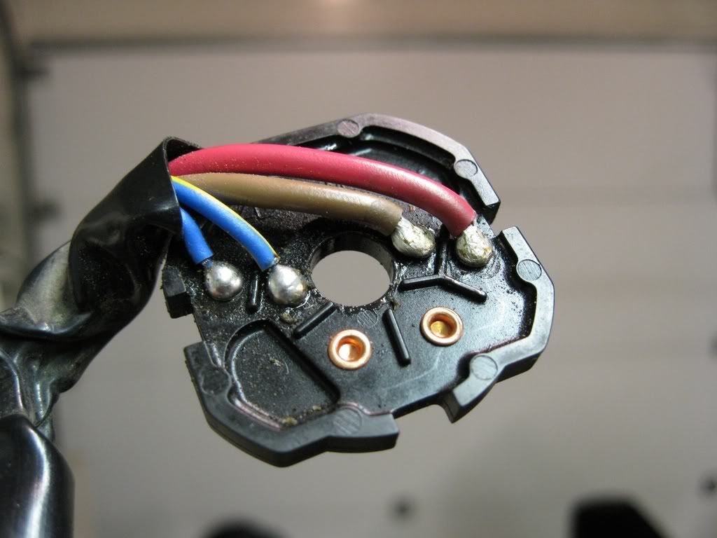
The solder contacts, mine were intact...
IMG_0030.jpg


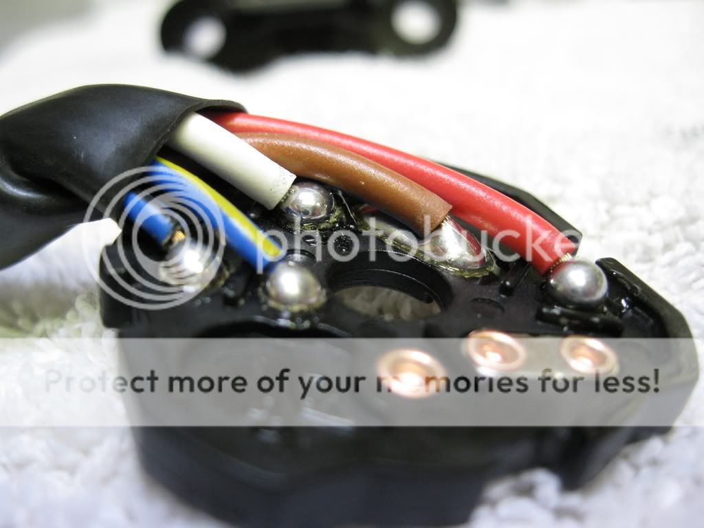
The recall switch solder contacts...

IMG_0045.jpg
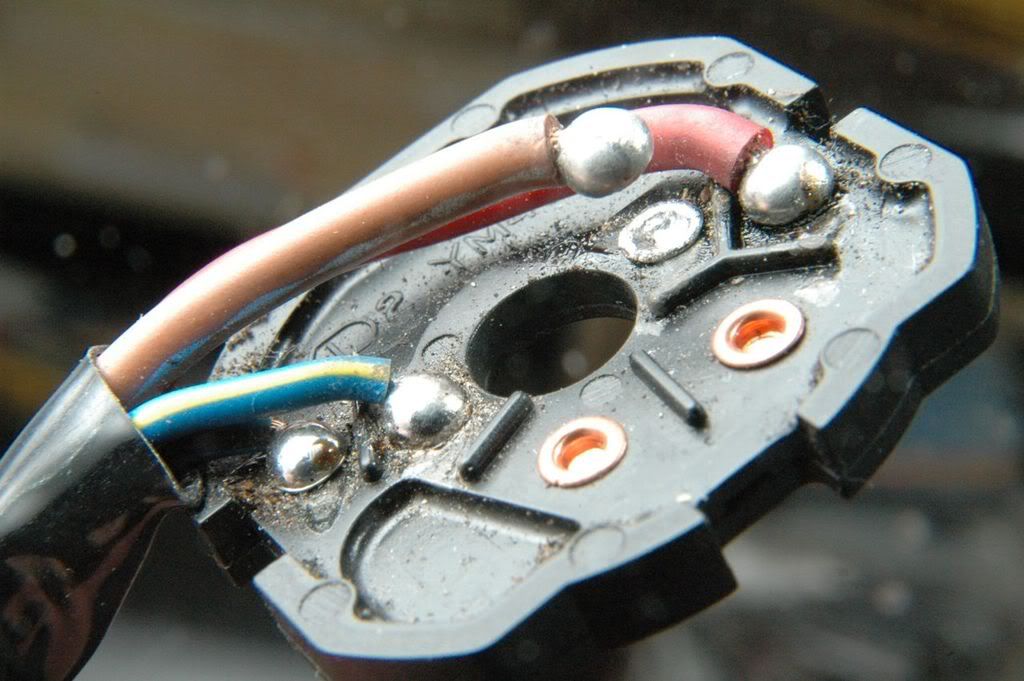
Here is the failed solder contact from my '04.

failedswitch.jpg


Brodie's new ones are mucho better. Look how big that solder blob is on the brown wire. Best I can tell, my replacement switch ($175) is not of the new design. I paid a locksmith to re-key it so I wouldn't have to carry a second key. What I also did, though, was to buy one of Brodie's relays and tuck it away in there between the new switch and the terminal block. Fits like it was made for it.

Nothing spoils your ride like having the ignition switch let go while you're splitting lanes on a Bay Area freeway at 5:15 p.m. on a weekday. It's also kind of hard on your laundry as you sweat out how to get that big motorcycle off the pavement without an engine with all those cars around you.

Brodie was a prince and expressed me a new harness and relay to get me back on the road.

I'm going to see if my dealer can get my switch included in the recall, even though my '04 reportedly does not come under the recall.

 
I'm not a big fan of that solution from Yamaha. For the current to split equally between the white and red circuits the resistance has to be identical in each circuit. If the contact surface of either circuit gets a little dirty adding a tiny bit of additional resistance current will be diverted to the other lower resistance circuit.
Maybe it'll be fine if one circuit carries 70% of the current and the other carries 30%. If the resistance of each circuit is almost identical in the beginning it'll likely change after many switch operations.

But, they may have added enough of a margin so it won't be a problem.
tru dat!--Also I don't see any improvements to the load side of the switch-still two contacts and one wire[brown]-am I wrong?..Wouldn't the overheating problem just move to the weakest link-the load side? I will keep the relay in the circuit..

 
Brodie,

Thanks for all the work to show what the new switch looks like. I'm wondering about the added wire?? Where does it go ? and will your relay kit work with this new wire in the circuit? Thanks for any light you can put on this.

 
Kudos for mamayamaha to step up with an improved switch design, and a BIG THANKS to Brodie for this excellent picture/write-up. :clapping:

 
Last edited by a moderator:
Thanks for the great write-up! I had my new switch installed on Tuesday. The only difference I noted from yours was a red stripe around the keyhole. I asked the tech about it and he said that was the new switch.
Just another case of the dealership shop-tards not able to follow instructions.

step 21 on Pg 6:

Remove the "red circles" protective cover from

the top of the main switch. The new main switch

is now ready to be installed on the upper triple

clamp.

 
As to the new switch, and what makes it better: The overheating of the solder joints was due to the large amount of current passing through the resistance of the switch's contacts. They would be the spot that has the most resistance in the circuit and would develop the heat.

I've taken one of Brodie's pictures and annotated the switch contacts with what I believe is the way the wiring colors are below:

2994341080098858932S600x600Q85.jpg


I believe that the big solder glob under the brown wire (see the view of the wire side of the contact plate) is a jumper between the larger oval and smaller oval contact pads, as I have indicated above with a white line.

What that means is that the 3 point wiper shorts the large oval brown pad and the large oval red pad together, same as always. And now one of the two point wipers (which were previously unused) shorts the smaller oval brown pad to the round white. This means that , not only do we get twice as many contact points, the contacts are on different wipers in the plastic carrier.

There really was no need to increase the number or gauge of the physical wires, just decrease the current through the each contact. In fact, I'm very surprised that they added an entire new white wire back to the connector. THat really makes no sense to me. All they needed to do was to jumper from the Red pad to the White pad somehow.

 
good information brodie... anyone who would tear into the new switch to document the differences is uber dedicated to the art of ownership! and we're all better off for it.

thx/ al

 
Thanks for the great write-up! I had my new switch installed on Tuesday. The only difference I noted from yours was a red stripe around the keyhole. I asked the tech about it and he said that was the new switch.
Just another case of the dealership shop-tards not able to follow instructions.

step 21 on Pg 6:

Remove the "red circles" protective cover from

the top of the main switch. The new main switch

is now ready to be installed on the upper triple

clamp.
Thanks Fred, I guess my tech didn't read that step! I'll remove it before I head home.

 
I'm not a big fan of that solution from Yamaha. For the current to split equally between the white and red circuits the resistance has to be identical in each circuit. If the contact surface of either circuit gets a little dirty adding a tiny bit of additional resistance current will be diverted to the other lower resistance circuit.
Maybe it'll be fine if one circuit carries 70% of the current and the other carries 30%. If the resistance of each circuit is almost identical in the beginning it'll likely change after many switch operations.

But, they may have added enough of a margin so it won't be a problem.
Bordie thanks for your efforts in documenting the changes in the new switch. I tend to agree with Constant Mesh about the limitations of the Yamaha solution to this problem. I am still a firm believer that the best (most important) thing Gen II owners can do (assuming their original IS is still OK) is to install the Brodie Bypass Relay (BBR), this is the real and permanent solution, independent of future load changes, dirt, wear, whatever...

Since to my knowledge my IS is still OK and I've installed your BBR I will be holding off with the recall until I can find a Yamaha dealer in whom I have even the basic level of confidence - not that likely around these parts though.

 
Brodie, Thanks for all the work to show what the new switch looks like. I'm wondering about the added wire?? Where does it go ? and will your relay kit work with this new wire in the circuit? Thanks for any light you can put on this.
Rick

I designed my relay with the same connectors Yamaha uses. It is a direct plug and play device. I knew that when Yamaha came out with their recall they would not disturb the connector in the main wiring harness.

In short - Yes - my relay does indeed work with the new white wire in the circuit.
I know this for a fact because I drove the bike home from my dealer. The white wire and the red wire shares the same terminal in the white connector. They both get switched on to the brown wire's contacts on the wiper plate. Yamaha must have considered it easier (less costly) to manufacture it this way instead of jumping the 2 terminals at the wiper plate.

You have my ignition Relay Harness,

Get the recall switch.
Then GO RIDE!


:bike:

Brodie

 
Brodie, thanks for the analysis and info - you really help the forum and its members.

I do have a question for you. I'm considering purchasing the Heli-bar riser triple tree and was wondering if the recall switch kit's replacement screws used to attach the switch to the triple tree are security screws that I'll have to drill out when I install the Heli-riser triple tree or are they normal screws?

 
Brodie, thanks for the analysis and info - you really help the forum and its members.
I do have a question for you. I'm considering purchasing the Heli-bar riser triple tree and was wondering if the recall switch kit's replacement screws used to attach the switch to the triple tree are security screws that I'll have to drill out when I install the Heli-riser triple tree or are they normal screws?
Yes. The screws that come in the switch kit are the security type. You can just ask the shop to leave the heads un-twisted off, so that you can install your new riser plate afterward. Or have them install it for you.

 
Thanks Fred, I'll ask the shop not to beak off the heads. I would ask them to install it but 1) I don't have it now and 2) I generally like to do all my farkles myself. It's a bonding experience I have with my bike. ;)

 
Thanks for the great write-up! I had my new switch installed on Tuesday. The only difference I noted from yours was a red stripe around the keyhole. I asked the tech about it and he said that was the new switch.
Anyway, I've got the bypass and the new switch so I should be good to go! :yahoo:

Just some much needed FYI here. That red stripe is a plastic decal that is to be REMOVED after installation or when a new bike is prepped for sale. If its left in place you might find it stuffed inside your lock tumblers someday and your bike will NOT start. We've had more than one bike with switch problems traced back to that little piece of plastic. Don't ask me what it is really for other than to let newbie riders know where the key goes and which way to turn it. B)

 
Top