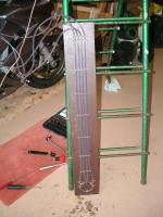
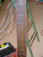
Tools for TBSync

Yamaha FJR Motorcycle Forum

Help Support Yamaha FJR Motorcycle Forum:

This site may earn a commission from merchant affiliate links, including eBay, Amazon, and others.
Good pics and the video is very insightful. Was that video while you were making an adjustment or is the pressure that inconsistent?

OK, we do the math (I was too lazy) and a two inch difference in water column height is only 0.072 psi so inconsistent is relative :rolleyes:

Edit: Oh! and you mention the 1/4 CTS tubing was too big for the bike connection. What size tubing did you use?

Wondering if ATF (i.e. - a denser fluid) would reduce the bouncing? :unsure:

Still looking for answers to the previous questions: What is 'typical' (pre-balance) and max (worst case assuming everything stays connected) differentials?

 
Last edited by a moderator:
OK I think I know what to do with these, do I swallow 1 or 2 of those things before I start the sync? :blink: Seriously though, I am not mechanically inclined so could someone dumby this up for me? Where do you put the brass thingy's and what size plastic hose would I need, because I read somewhere that the 1/4 inch hose might be too big?? Thanks in advance.

 
OK I think I know what to do with these, do I swallow 1 or 2 of those things before I start the sync? :blink: Seriously though, I am not mechanically inclined so could someone dumby this up for me? Where do you put the brass thingy's and what size plastic hose would I need, because I read somewhere that the 1/4 inch hose might be too big?? Thanks in advance.
I'm liking CMs suggestion and his logic to eliminate the PVC tubes. The restrictors need to go inline on each tube between the bike and the manometer. It would appear to me that they could be inserted directly into the vinyl tubing but may need to downsize the tubing for proper fit.

I'm shopping today so I'll let you know what I get!
Yes please do. Thanks for the explanation. I just cant see spending 100$ to get this done!

 
I've also built my own. Made it as simple as possible, the significant difference to most home-made ones is that I use engine oil as the working fluid.

This is self-damping so needs no real restrictor, I've just put some adjustable clips on the pipes, but these aren't needed.

Also if any does get sucked into the engine, it will go in much more slowly than water so is less likely to form a hydraulic lock before you see what's going on.

Works well for me.

(Click on image for larger view)

Prior to filling . . . . . . . . . Oil in, engine running


My pictorial TBS procedure here.

 
Last edited by a moderator:
So I look at these and wonder, as the differentials seem to be only a couple of inches, why are these things made 3 to 4 feet tall?
Because mercury weighs 13.5 times the weight of water, so 1 PSI corresponds to approx 2 inches of mercury or 27.7 inches of water (or something like 34 inches of engine oil).

 
Last edited by a moderator:
I made a home made TBS tool, but wanted to confirm calibration so I bought the actual TBS tool.

If anybody is located around the South Central PA and has interest in a home made TBS tool, PM me.

Cost me $55 + time to build. I'll let it go for $40

 
Calibrate a relative instrument?

Ahhh well, yes. It seemed my synch was pretty far off and thought it might have been some type of leak or what not within the makeshift tool. Come to find out, the bike was just that far out of whack.

I just needed to compare it with a known relativity. ;)

 
So I look at these and wonder, as the differentials seem to be only a couple of inches, why are these things made 3 to 4 feet tall?
Because mercury weighs 13.5 times the weight of water, so 1 PSI corresponds to approx 2 inches of mercury or 27.7 inches of water (or something like 34 inches of engine oil).
I understand the pressure differential will displace lighter fluids a greater amount. I could have done that math but it doesn't tell me why I only see differentials of a couple of inches of water or ATF in the photos and videos. I think I read that the specified acceptable vacuum is within a range of 60mmHg. This is ~32in of water. But, has anyone seen differences between cylinders greater than a few mm of Hg or a couple of inches of water?

 
OK, I spent a little more than I needed to but that's the way I roll! :D

Here is my bottom manifold:

IMG_0208.jpg


This is made up of a 4 port manifold ($6.99), 4 barbed fittings (2/$1.99) and 1 plug ($0.89)

Here is part of my top manifold:

IMG_0209.jpg


This is made up of a barbed male fitting (2/$1.99) and a barbed female fitting (2/$1.99)

This allows disconnection of the tubing, that goes to the bike, when not in use and allows for insertion of air flow restrictors for pulse damping and backflow protection.

I picked up 30' of 1/4" tubing at $0.19/ft.

I still need to figure out the flow restrictors.

Once I determine how tall to make the manometer, I'll put it together and post more pics.

 
Last edited by a moderator:
OK, I spent a little more than I needed to but that's the way I roll! :D
Here is my bottom manifold:

IMG_0208.jpg


This is made up of a 4 port manifold ($6.99), 4 barbed fittings (2/$1.99) and 1 plug ($0.89)

Here is part of my top manifold:

IMG_0209.jpg


This is made up of a barbed male fitting (2/$1.99) and a barbed female fitting (2/$1.99)

This allows disconnection of the tubing, that goes to the bike, when not in use and allows for insertion of air flow restrictors for pulse damping and backflow protection.

I picked up 30' of 1/4" tubing at $0.19/ft.

I still need to figure out the flow restrictors.

Once I determine how tall to make the manometer, I'll put it together and post more pics.
thanks for keeping us posted. Not sure what exactly what that manif0ld is but I'm sure it'll become clear when's its done....it looks cleaner than other tools Ive seen....where did you get the manifold?

edit....I think i figured out the maniforld thing...it replaces all the pulumbing on the bottom and eliminates all the T's?????

 
Last edited by a moderator:
edit....I think i figured out the maniforld thing...it replaces all the pulumbing on the bottom and eliminates all the T's?????
You got it! Think of the manifold as a 4 way connector. Parts from a store called Princess Auto up here in Canada. You may be able to find such a thing in stores that sell a lot of compressors and air hose accessories.

 
QUOTE (FJRGuy @ May 13 2010, 07:47 AM) <{POST_SNAPBACK}>

QUOTE (mcatrophy @ May 11 2010, 01:25 AM) <{POST_SNAPBACK}>

QUOTE (FJRGuy @ May 11 2010, 03:03 AM) <{POST_SNAPBACK}>

So I look at these and wonder, as the differentials seem to be only a couple of inches, why are these things made 3 to 4 feet tall?

Because mercury weighs 13.5 times the weight of water, so 1 PSI corresponds to approx 2 inches of mercury or 27.7 inches of water (or something like 34 inches of engine oil).

I understand the pressure differential will displace lighter fluids a greater amount. I could have done that math but it doesn't tell me why I only see differentials of a couple of inches of water or ATF in the photos and videos. I think I read that the specified acceptable vacuum is within a range of 60mmHg. This is ~32in of water. But, has anyone seen differences between cylinders greater than a few mm of Hg or a couple of inches of water?

Can't answer your "what has anyone seen" question, but when things go slightly wrong
unsure.gif


(click on image for larger view)


At least there's some length to deal with it
biggrin.gif
.

This happened because of a leak in one of my T-joints, but could equally be one of the vacuum connections to the engine leaking. During my actual adjustments, I only saw a couple of inches of difference.

 
Last edited by a moderator:
...During my actual adjustments, I only saw a couple of inches of difference.
Thanks!

I'm thinking with a restrictor in line, and proper testing of the tubes beforehand, a 2' manometer offers plenty of operating range. I appreciate your inpuy

FJRguy I sent you a PM
 
Last edited by a moderator:
I've also built my own. Made it as simple as possible, the significant difference to most home-made ones is that I use engine oil as the working fluid.
This is self-damping so needs no real restrictor, I've just put some adjustable clips on the pipes, but these aren't needed.

Also if any does get sucked into the engine, it will go in much more slowly than water so is less likely to form a hydraulic lock before you see what's going on.

Works well for me.

[SIZE=8pt](Click on image for larger view)[/SIZE]

Prior to filling . . . . . . . . . Oil in, engine running


My pictorial TBS procedure here.
I followed your design for the most part and it worked like a charm...I actually mounted in on my garage wall. It was incredibly stable.


Latest posts

Top