I am going to install Denali DM LED lights and would like advice on which switched power source is best to connect the on/off button wire? I was thinking perhaps the aux power outlet in the glove box. Is that a switched line?
You are using an out of date browser. It may not display this or other websites correctly.
You should upgrade or use an alternative browser.
You should upgrade or use an alternative browser.
What switched power source?
- Thread starter art miller
- Start date


Help Support Yamaha FJR Motorcycle Forum:
This site may earn a commission from merchant affiliate
links, including eBay, Amazon, and others.
Twigg
Just an old, bald man!
The power outlet in my glove box is "Always On", however, it was fitted by a PO and might not be typical.I am going to install Denali DM LED lights and would like advice on which switched power source is best to connect the on/off button wire? I was thinking perhaps the aux power outlet in the glove box. Is that a switched line?
Fairly easily accessible is the power connector for the windshield auto-retract. I believe that is switched and should be fine to switch a relay.
bigjohnsd
2021 BMW R1250GSA
He has a Gen III and no retract.
Pterodactyl
Well-known member
Are you looking for a place to attach a relay? I used the high beam circuit as the switched power source for one set of aux lites on my bike. I ride with my high beams on during the day so the aux lites are on, but at nite they go off when I dim the lites. The second set of aux lites are run off a fuse block with a built in relay. The block is under the seat so I use the tail lite circuit as the switched circuit for that relay. That set of lites that is powered by the fuse block is always powered if the bike is running. There is an on/off switch for the second set of lights as well
Last edited by a moderator:
Mudslide Miller
Well-known member
For my trigger wire on the Kristas I used the wire going to low beam lights just below the relay, which is located under the dash plastic on the left side. You get power AFTER the bike starts & the low beams kick on. Wherever you decide to get your power, I recommend using posi-taps to splice into your source wire. Easy to use, especially in hard to get to places.


$64.99
Edwards Oil Change Kit fits 2003-2020 Yamaha FJR1300 Sport Touring
Edwards Motorsports & RV's

$79.95
Harley-Davidson Water-Resistant Travel Hybrid Duffel Bag/Backpack - Black
Wisconsin Harley-Davidson


$159.99
FLAVOR Men Brown Leather Motorcycle Jacket with Removable Hood (Large (US standard), Brown)
FLAVOR Leather

$216.94
410-54267 Replacement for 410-54267 Starter for YAMAHA FJR1300 03-06 FJR1300P 18 18765
Otisdelilah Auction


$197.39
$209.99
Milwaukee Leather SH1408 Men's Sporty Crossover Vented Black Motorcycle Leather Scooter Jacket - Large
Amazon.com


$19.99
MOREOK Winter Gloves -10°F 3M Thinsulate Warm Gloves Bike Gloves Cycling Gloves for Driving/Cycling/Running/Hiking-Black-L
MOREOK-US (Ships from USA)


$198.86
410-54267 Replacement for 410-54267 Starter for YAMAHA FJR1300 03-06 FJR1300P 18 18765
Otisdelilah Auction


$7.49
$14.99
WTACTFUL Tactical Gloves for Men, Summer Motorcycle Cycling Motorbike Driving Riding Hunting Outdoor Work Fingerless Half Finger Gloves Men Women Black XL
WTACTFUL Trading Co.,Ltd


$98.16
25-1775 Replacement for All Balls Wheel Bearing Kit (25-1775) for Yamaha FJR1300 03-16 FJR1300ES 14-18
Otisdelilah Auction


$24.37
Fuel Tank Sticker Motorcycle Stickers for Yam&aha FJR1300 FJR 1300 Tank Pad Protector Decal Emblem Side Fairing Symbol Adventure
nanyangshixianpushangmaohanggerenduzi
Mudslide Miller
Well-known member
I realized after I responsed, that your Denali's may or may not use a trigger wire. My actual power source is coming through my PDM60 fuse block, which is powered directly from the battery. The trigger wire at the low beam lights just tells it to go ahead and send that power through only after the low beam lights kick on, but you can still tap in to the low beam wiring on your hot side if you are just running a direct power source to the lights. Is that power source going to go through a relay and seperate switch?
I (finally) just had to do this on my 2014, needed for my heated gear and LR4 Aux lights. Here's how I decided to go:
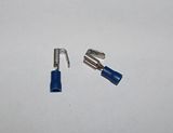
For an ignition switched 12V power relay trigger I just used the harness power wire going to the horn (brown). Very easy to piggyback a spade lug off of that using one of these solderless connectors and no need to remove any panels to get at it. (I did insulate the exposed metal on the female side with shrink tubing.) The current draw to energize a 12V relay is minuscule and the horn circuit is already appropriately fused for the added load via the "Signal" fuse.
The actual power wire being switched to the Aux Lights should come directly from the battery to the relay, and be appropriately fused for the gauge of wire being used up to the next fuse. I ran a 10 gauge wire, fused at 30A to the relay, and the output of the relay goes to a short, Euro-type terminal strip one of the below cut in half. (available at radio shack)

Daisy chain the back side together with jumper wires...
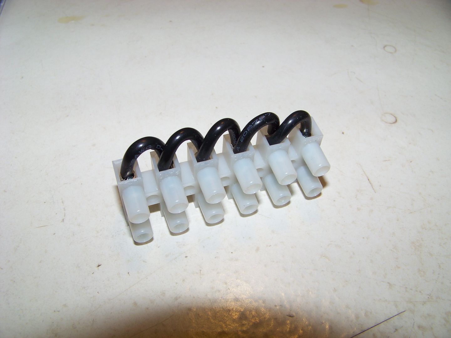
... and then insert the switched power feed from the relay into any one of the slots. (Red wire was just a test fit for the feed wire, Black wire would be one of the load slots)
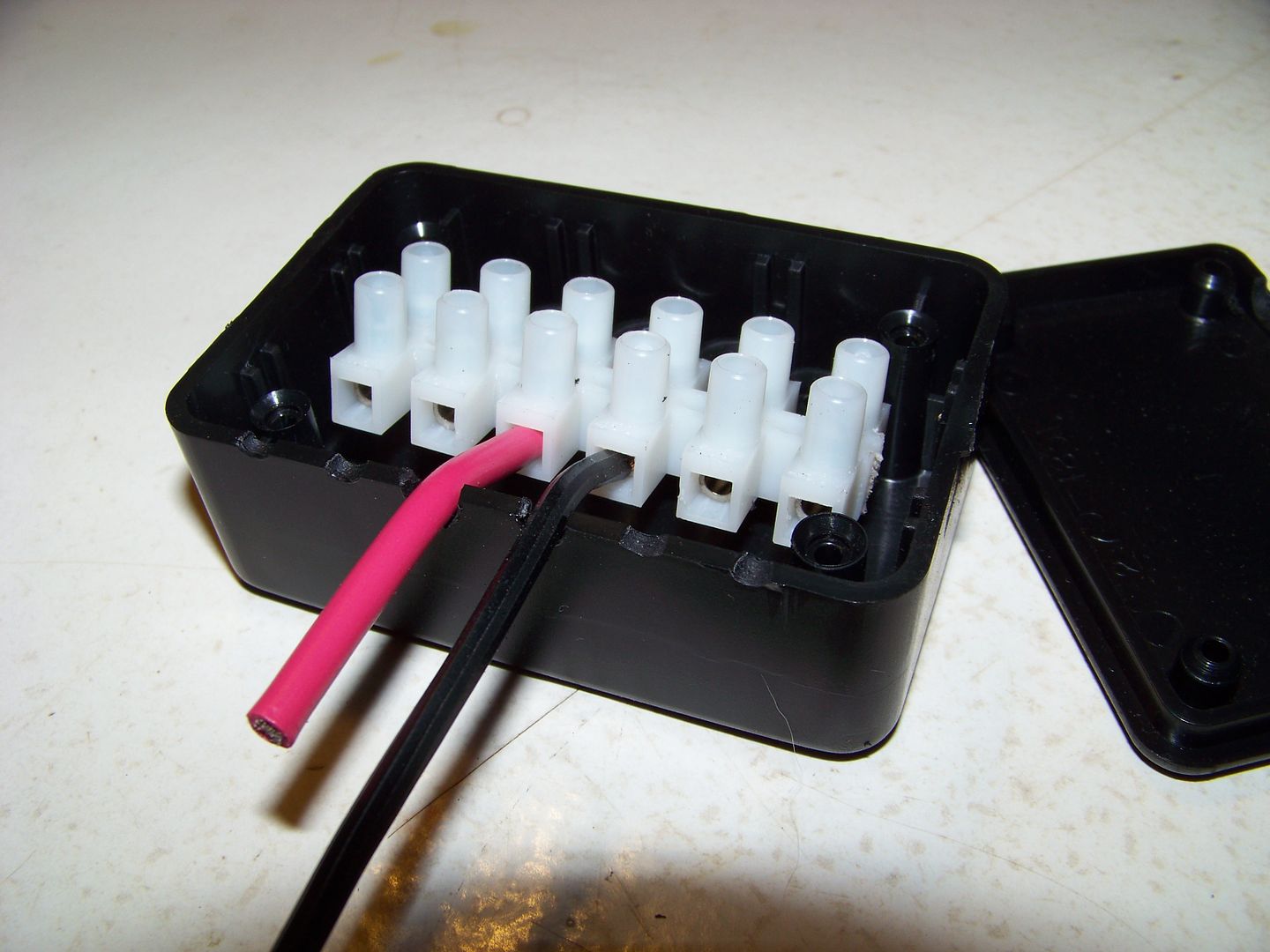
I fused each of the runs going off to each of the individual loads with inline automotive-type fuses. You can either enclose the short terminal strip in a small project box, like above, or just leave it bare and ty-wrapped to something in the confines of the faring. There is no exposed metal with power on it, except for the well recessed screw heads.
I drew up a diagram for wiring a 12V relay to power some aux lights with an LED Dimmer module that Justin now uses on his LEDriders web site:

In this case my Euro Terminal strip would be located in the red wire between the Relay 87 terminal and the Dimmer Module.
For an ignition switched 12V power relay trigger I just used the harness power wire going to the horn (brown). Very easy to piggyback a spade lug off of that using one of these solderless connectors and no need to remove any panels to get at it. (I did insulate the exposed metal on the female side with shrink tubing.) The current draw to energize a 12V relay is minuscule and the horn circuit is already appropriately fused for the added load via the "Signal" fuse.
The actual power wire being switched to the Aux Lights should come directly from the battery to the relay, and be appropriately fused for the gauge of wire being used up to the next fuse. I ran a 10 gauge wire, fused at 30A to the relay, and the output of the relay goes to a short, Euro-type terminal strip one of the below cut in half. (available at radio shack)
Daisy chain the back side together with jumper wires...
... and then insert the switched power feed from the relay into any one of the slots. (Red wire was just a test fit for the feed wire, Black wire would be one of the load slots)
I fused each of the runs going off to each of the individual loads with inline automotive-type fuses. You can either enclose the short terminal strip in a small project box, like above, or just leave it bare and ty-wrapped to something in the confines of the faring. There is no exposed metal with power on it, except for the well recessed screw heads.
I drew up a diagram for wiring a 12V relay to power some aux lights with an LED Dimmer module that Justin now uses on his LEDriders web site:
In this case my Euro Terminal strip would be located in the red wire between the Relay 87 terminal and the Dimmer Module.
Last edited by a moderator:
Intech
Mr. Camping Meet
I posi-tapped the power wire to the glove box. Unless it has been modified it is switched by the ignition. I use that feed to power the relay on my fuzeblock.
Pterodactyl
Well-known member
[REDACTED]
Last edited by a moderator:
bigjohnsd
2021 BMW R1250GSA
Pterodactyl
Well-known member
If this forum would allow a poster to delete his/her post, then things like my last post would not need to happen..... period.
ionbeam
2 FUN
Well, if you can't delete a post then post this, the same as a post wipe.If this forum would allow a poster to delete his/her post, then things like my last post would not need to happen..... period.

Pterodactyl
Well-known member
Okay, WILCO. I always wanted to know what it would be like to be in the NSA or CIA.

Gmann
Well-known member
Now that cracked me up this morning! Almost spilt my coffee on me. Thanks Pterodactyl!
Warpdrv
Well-known member
I know someone was using a lead behind panel on the left side under the seat..... for taping into the for a switched source....
Any pictures of that would be nice - to hook up my fuzeblock under the seat....
Any pictures of that would be nice - to hook up my fuzeblock under the seat....
You could tap into the tail light (not brake light) wire. It runs in the bundle (have to split that open) up the left side under the seat. Wire color you are looking for is the blue w/ red tracer. It also goes to the plate light.
I dug into that bundle to tap into the brake light wire for my Whelen LIN3 3rd brake light.
I dug into that bundle to tap into the brake light wire for my Whelen LIN3 3rd brake light.
Last edited by a moderator:
Thanks for all the info. I will check the glove box outlet to see if it is switched. If it is I will piggyback off that terminal. I plan to mount the off/on switch on that side. The Denali DM lights are very low drawl and low beam only. All the wiring is neatly assembled in a harness with relay. I do not ride a night. Adding these for more cager visibility.
I can tell you that the power port definitely is ignition switched.
Last edited by a moderator:
metalman
Well-known member
Similar threads
- Replies
- 14
- Views
- 962
- Replies
- 14
- Views
- 2K