Link to all my Gen II mods
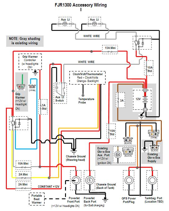
As you add lots of electrical farkles, you may want to consider creating a record of how you wired it, to help yourself or your mechanic later. Here’s mine, and it was also a big help in designing the system in the first place. Hopefully I never need it for trouble-shooting, though!
I just used MS-Word to create it. I first extracted JPG images of the various standard components from the schematic (using MS-Paint) building a “library” to use as building blocks for my new circuits (relay, fuses, switches, etc.). Then I pasted them in as needed and added lines (with proper color coding) representing the various wires. Lastly, I added notes to help me remember stuff later on.
With the attached image, you already have a JPG image that can be used to extract your components as I did.

Last edited by a moderator:


