I do not have service manual for Gen. 3. (Have one Gen. 2). Throttle bodies have changed for Gen. 3 and I don't want to cause a problem. Can anyone give me information on how to set these up? I have the gauges and always adjusted my Gen. 2 previously.
You are using an out of date browser. It may not display this or other websites correctly.
You should upgrade or use an alternative browser.
You should upgrade or use an alternative browser.
2013 FJR 1300 synchronizing throttle bodies
- Thread starter FJRbobliz
- Start date


Help Support Yamaha FJR Motorcycle Forum:
This site may earn a commission from merchant affiliate
links, including eBay, Amazon, and others.
SouthernCruizer
Is it Beer:30 yet?
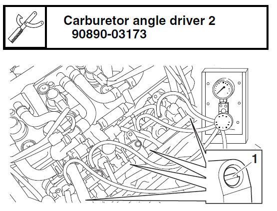
you will use the same gauges/tools/ procedures as you did for your Gen II...the reference throttle body has a white(ish) paint mark on the adjusting screw head.I do not have service manual for Gen. 3. (Have one Gen. 2). Throttle bodies have changed for Gen. 3 and I don't want to cause a problem. Can anyone give me information on how to set these up? I have the gauges and always adjusted my Gen. 2 previously.
SouthernCruizer
Is it Beer:30 yet?
pics may help....
Kaelaria
Well-known member
Find the white painted screw to find your master. https://twowheelobsession.com/2014/08/27/throttle-body-sync-tbs-yamaha-fjr-1300-es/
Bungie
FrostBack #2 - IBA # 44620
The adjusting screws no longer point up to the 10am position when viewed from behind.
They point straight backward and a bit of a bitch to get to.
They point straight backward and a bit of a bitch to get to.
I just did the adjustment on my 2015ES. SOME OBSERVATIONS: the obsession video looks a whole lot easier than the job really is!. It is PITA from the beginning to the end. I started by purchasing the manometer gauge he uses in his video from the UK. Cost USD 106 to my door. Shipping time 10 days to my door. So far so good. The actual job: masking all the pertinent areas with blue masking tape: top of tank, front of tank, side fairing panels, etc. about one hour. Removal of stem mounted GPS system 20 minutes without scratching everything in the process. Removal of the (in my case) black tank plastic surround at the front seat. Described in the video as just clipped in at the front and easy to remove after removal of the plastic pins and the two screws. Hah, took around an hour to get those easy in the rubber grommet located tabs out! They are not lubricated and they have a hook at the front. So they are strictly one way. And there is no wiggle room without removing the side fairing. Lots of patience and time required. Lifting the tank, disconnecting and reconnecting the wires, removing the t-bar, bending the heat shield up, all pretty easy. BUT after you are all done, there is virtually No Room to do any work!! It took quite awhile to actually locate the adjustment screws and even longer to cut off an existing, wide and thin enough screw driver to serve as an adjustment tool. Someone already mentioned here that the screws now point almost straight back and slightly upwards. That is about the worst location possible because all sorts of wires and hoses run crisscross all around there. I mad several dry runs ( engine off and cold) to get the "feel" of the location, cause lateron when everything is hot under there you don't want to be groping around there. It'll bite you! NOW TO THE FUN PART: I now just took a small needle nose plier and just tore the little spring clips off. There is no decent way to get at them and remove them neatly for future use, unless you remove the entire tank. THEY COME OFF BENT ANYWAY. I than threw them into the trash. Then I pulled the rubber caps off and examined them. They look substantial. They are rugged and formed to hang onto the burled tubing end of the air tube. Why those silly spring clips. This is a vacuum connection. So If anything it sucks the rubber boot even tighter onto the tube. ( just in case I bought 10 rubber caps and 10 spring clips from the dealer, should I need any. Never did). The connection of the gage was straightforward and once connected, warmed up, the darn throttle bodies were perfectly within specs. I adjusted them a little back and forth, just to see if they in fact moved and they did. The reference TB in my case was clearly marked as the left or number one cylinder. I reassembled everything leaving off those silly spring clips, rerouted some accessory wiring, while I was in there. The hardest part of the re-assemble was the plastic tank surround at the seat. Got everything back together and went for a short 200 mile test run. Runs just like it did before!!!
Have fun
Have fun
petey
Well-known member
^^^^OMG...Wemi you made a job of it...

Kaelaria
Well-known member
Wow talk about a mountain out of a molehill...
Here is an article I copied and saved and I'm sorry the author wasn't saved but I think it was once called the unauthorized method of FJR TBS.
Definitely worth a read to better understand the concept of synchronization. It works too!
Here is the "ridiculous procedure" for Synchronizing the FJR Throttle Body Linkages. I rewrote it to make the instructions mo clear.
Adjusting the TB air screws alone does not provide the most effective TB sync because they only compensate for air flow at idle. Most of your riding takes place at higher RPMs. The throttle valves (butterflies) of each throttle body need to be in sync with each other at high (off-idle) RPM.
This procedure is not covered in the factory manual. However this procedure is common and dealers that know what they are doing (and are willing to take the time) perform this adjustment on many multi-cylinder bikes. Having the TB’s in sync at cruising speeds (not just at idle) makes a huge difference in engine smoothness and vibration.
You should not have to adjust the individual throttle stop screws to achieve this. This assumes that the throttle stop screws have not been grossly misadjusted at the factory (guy on the flow bench had one too many bottles of Sapporo the night before) or the lock nuts have come loose.
(sorry can't copy the image. pm me and I'll send the document)
To get the engine’s intake tracks in sync the four throttle body plates need to be adjusted to match each other’s air flow. The throttle bodies are linked in pairs. TB’s #1 & #2 have an adjustment screw that adjusts their linkages. TBs #3 & #4 have a different adjustment screw that adjusts their linkages. The two pairs are linked together by a third adjustment screw.
This is a simple procedure but does take patience. The image above shows TBs #1 & #2 on the left and the linkage adjustment screw for this pair is circled in green. TBs #3 & #4 are on the right and their adjustment screw is circled in yellow. The blue circle is the approximate location of the linkage screw that adjusts the two pairs together. This screw is only accessible when the throttles are twisted about ¾ of the way open—so the engine has to be off to gain access to this screw. Here’s how to make the adjustments:
1. Get the engine hot by going for a short ride. When you are at 4200 RPM (Gen I, the rpm number will be slightly lower for Gen IIs) in 3rd or 4th gear, squeeze you heals against the frame to feel the level of engine vibration. This highly precise measurement will be used later to determine how good a sync job you did.
2. Raise Tank and connect sync tool.
3. Turn all four air adjusting screws on each throttle body (not the throttle linkage screws) in until they are lightly seated.
4. Back each screw out 1 turn
5. You may want to place a large fan in front of the radiator to keep things cool (including you).
6. Start the engine.
7. The TBs will probably be out of sync at idle. The actual vacuum levels that your sync tool shows does not matter—we’ll fix idle sync later in the procedure.
8. REVING THE ENGINE Slowly rev the engine up to around 4000 RPM while watching your sync tool. What you are looking for is even vacuum levels as engine speed increases. If you try to perform to sync the TBs with the engine speed steady (say at 4000 RPM) you will find that the vacuum levels between each TB will never be in sync no matter how many adjustments you make. It is more important for vacuum levels to be even during moderate, smooth, engine acceleration and not at a steady throttle setting. You will have to rev the engine multiple times to get a feel of where the vacuum levels are at for each throttle body.
9. Using the butterfly sync screw between TBs #3 and #4 (Yellow Circle) adjust the vacuum level so #3 and #4 are the same when you accelerate the engine as described in Step 8, “REVING THE ENGINE above. This will take several tries. You may not get them exactly even either, but get them as close as you can (usually within 1 cm of Hg.).
10. Now perform the same procedure on TBs #1 and #2 (Green Circle). You may have to rev the engine half a dozen times to get them close.
11. With vacuum levels for TB pairs #1/#2 and #3/#4 matched it’s time to sync the two pairs of TBs together.
12. Rev the engine as described in step 8, REVING THE ENGINE while watching the two pairs of TBs. If they are off by more than 1 cm or Hg., an adjustment is needed.
13. The adjustment screw can only be accessed with the engine off. The screw is located between the two pairs of TBs (Blue Circle with Arrow). (The throttle has to be opened about ¾ of a turn to get a screw driver on the screw). Turn the screw about 1/8 of a turn (either direction) and restart the engine.
14. Check the balance (vacuum level) between the two pairs of TBs. Shut the engine off and readjust as many times as needed. If turning the third screw 1/8 of a turn in one direction, turn the screw the other direction and check vac levels again. (By now you and your FJR’s cooling system will appreciate the large fan you are using, step 5.)
15. When the two pairs of TBs are even (when you smoothly rev the engine) you are finished with this step. To be too anal about how close the vacuum levels are. Get them as close as you can.
16. Now let the engine idle. Adjust the idle speed to 1000. The tach on the FJR is very accurate. I checked it against a $500 electronic sync tool that counts the vacuum pulses during the intake stroke of cyl #1 and then generates an RPM signal on the tool.
17. Now it’s time (finally) to adjust the airscrews on each TB. Use cyl #3 as reference and adjust the other cylinders to the same vacuum level as #3. The actual level does not matter (I know, everyone seems to be hung up on how may cm of HG., but it really doesn’t matter as long as idle speed is kept at 1000 RPM.)
18. Make a final idle adjustment (1000 RPM) and you done. If after syncing the TBs with the airscrews you can’t get the idle speed to come down to 1000 rpm, DON’T KEEP BACKING THE IDLE ADJUSTING SCREW OUT because is will unthread from the throttle linkage. If idle speed won’t come down to 1000 rpm the TB airscrews all need to be turned in ¼ to ½ turn (make sure you turn them in all the same amount). Now the idle adjusting screw will allow you to adjust the idle speed to down to 1000 rpm.
19. Last step. Go for a ride and check engine vibration at 4200 RPM (Step 1), it should be better than when you started. If it’s worse, you screwed up the adjustment. The amount of improvement really depends on how far out of the sync the TB linkage was before you started. When done correctly most of the vibration you normally feel at 4100/4200 RPM in fourth/fifth gear should be gone—at least it was on my 2005. Good Luck!
by FredW
(thanks excapefjrist)
Last edited by a moderator:
escapefjrtist
Searching for Dry Roads
TBS shouldn't be that difficult Wemi. Any pics of a GEN III with the tank up?
Unauthorized procedure ^^^^ above was put together by FredW.
--G
Unauthorized procedure ^^^^ above was put together by FredW.
--G
eg23232
Well-known member
This is why I paid a shop $200 to do if for me (and change the plugs).
Pterodactyl
Well-known member
It is not as difficult as portrayed above, by a far cry.
mcatrophy
Privileged to ride a 2018 FJR1300AS
A couple of pics of the TB area (I was more interested in spiders when I took these, so not very instructive):(Click on image for larger view)TBS shouldn't be that difficult Wemi. Any pics of a GEN III with the tank up?
Unauthorized procedure ^^^^ above was put together by FredW.
--G


YummYam
Well-known member
Done my Gen II twice, including synching each pair and it's easier the second time around!
Got everything hooked up on my buddies Gen III ready to adjust but he was happy with the existing readings, so just bolted everything back up.
Got everything hooked up on my buddies Gen III ready to adjust but he was happy with the existing readings, so just bolted everything back up.
Bungie
FrostBack #2 - IBA # 44620
Cannot be done on a GenIII. Their are no throttle plate adjusters. Well, at least none visible. They may now be under the throttle body. Either way, likely can't be done.Here is an article I copied and saved and I'm sorry the author wasn't saved but I think it was once called the unauthorized method of FJR TBS.Definitely worth a read to better understandthe concept of synchronization. It works too!
Getting to the top of the engine is not difficult on a Gen3. Getting to the throttle body set screws is difficult, even after removing all the pairs hosing. Removing the spring secured caps was not difficult but did require a bit of patience and finesse. I'm glad my bike was still within specs because I do not know how I would have gotten to the #2 or #3 adjestment screws.
If anyone has an idea, or does it just require a flexible shaft screwdriver?
If anyone has an idea, or does it just require a flexible shaft screwdriver?
Bungie
FrostBack #2 - IBA # 44620
I bought a flexi-driver specifically for this job.
Totally useless, but at least now I have a flexi-screwdriver.
I ended up using a plain old jewelers screwdriver. Worked the treat, but #2 has to have the screwdriver threaded over and under various wire looms etc. Doable though.
Totally useless, but at least now I have a flexi-screwdriver.
I ended up using a plain old jewelers screwdriver. Worked the treat, but #2 has to have the screwdriver threaded over and under various wire looms etc. Doable though.
It is not technically difficult, just extremely awkward to work. As indicated by the posts below, others are experiencing the same issues with flex screwdrivers That don't work and not being able to do number 2 and 3 or leaving 3 out because they couldn't find the adjustment screw.TBS shouldn't be that difficult Wemi. Any pics of a GEN III with the tank up?
Unauthorized procedure ^^^^ above was put together by FredW.
--G
Like I indicated in my posts I sawed the handle off a fitting blade. That made the whole thing short enough to get into the little space behind the #2 and 3 screw. Like I said make a long dry run with the engine off and cold to locate all set screws. So when it's hot and running you can do it by feel.Getting to the top of the engine is not difficult on a Gen3. Getting to the throttle body set screws is difficult, even after removing all the pairs hosing. Removing the spring secured caps was not difficult but did require a bit of patience and finesse. I'm glad my bike was still within specs because I do not know how I would have gotten to the #2 or #3 adjestment screws.
If anyone has an idea, or does it just require a flexible shaft screwdriver?
Similar threads
- Replies
- 0
- Views
- 379
- Replies
- 7
- Views
- 704
- Replies
- 8
- Views
- 827
- Replies
- 5
- Views
- 716
- Replies
- 14
- Views
- 941