Lauren_TK
Well-known member
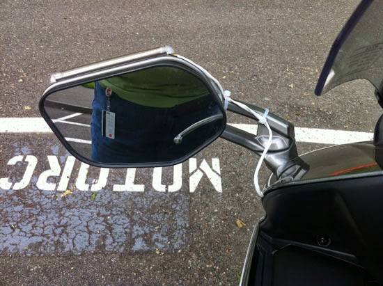
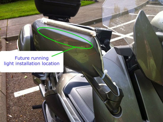
In a different thread, I mentioned that I was going to add LED Strips to my mirrors.
I started that project today.
I had to remove the inside center panel (again), and remove the side panels.
Actually, I only got as far as the left side of the bike.
However, I did get the left side working, and the right side will go together much easier tomorrow.
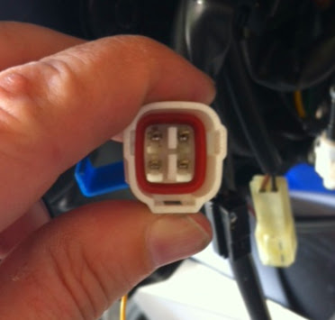
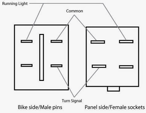
I don't have pictures of the final product yet, but I thought I would share the pin-out information on the Gen 3, as it seems to be different than the previous ones:

You will note that there are four pins and not three. The upper-right is ground, and the lower-right is the positive for the blinker. Upper-left is the lead for the running lights. I am not sure what the lower-left is for.
It was a little difficult to figure this out. I have leads with alligator clips, and I tried various combinations. It was the second to last combination of pin positions that let me get the running lights. With a quick swap of the leads, I knew which one was ground.
However, both the lower pins would let the LED strip blink once, and then never again. After a bit more futzing, I tapped into the wires, and then plugged harness to the signal wires, and I got a blinking LED array.
I'll post pictures of the finished product when it is finished. Sadly the bike is torn apart, and I haven't the energy to reassemble it tonight, so I'll be forced to take the cage tomorrow.
I suppose since I haven't installed the right side one yet, I don't want to reassemble anyway.
Time for dinner and a drink.
I started that project today.
I had to remove the inside center panel (again), and remove the side panels.
Actually, I only got as far as the left side of the bike.
However, I did get the left side working, and the right side will go together much easier tomorrow.
I don't have pictures of the final product yet, but I thought I would share the pin-out information on the Gen 3, as it seems to be different than the previous ones:

You will note that there are four pins and not three. The upper-right is ground, and the lower-right is the positive for the blinker. Upper-left is the lead for the running lights. I am not sure what the lower-left is for.
It was a little difficult to figure this out. I have leads with alligator clips, and I tried various combinations. It was the second to last combination of pin positions that let me get the running lights. With a quick swap of the leads, I knew which one was ground.
However, both the lower pins would let the LED strip blink once, and then never again. After a bit more futzing, I tapped into the wires, and then plugged harness to the signal wires, and I got a blinking LED array.
I'll post pictures of the finished product when it is finished. Sadly the bike is torn apart, and I haven't the energy to reassemble it tonight, so I'll be forced to take the cage tomorrow.
I suppose since I haven't installed the right side one yet, I don't want to reassemble anyway.
Time for dinner and a drink.


