Audiovox ccs100 cruise not working

Yamaha FJR Motorcycle Forum

Help Support Yamaha FJR Motorcycle Forum:

This site may earn a commission from merchant affiliate links, including eBay, Amazon, and others.

canadianfjrowner

Well-known member
Joined
Jun 2, 2012
Messages
76
Reaction score
3
Location
Ottawa, Ontario
I've installed the Audiovox ccs100 on my '07 AE (which is a pain because of location of servo). My problem is, it won't activate. The pinout test shows everything correct except that the brown wire will not hold power when the "ON" button is pressed. According to the pin out test this wire is supposed to remain at battery voltage when the "ON" button is pushed and go to " 0" volts when to "OFF" button is pushed. All other wires show proper voltage and ground when requested. I did install the relay in the brake wire circuit to make sure that unit sees good ground. There is proper vacuum to the servo. Because the servo is below the gas tank in behind the front fork, it is hard to access and see the diode inside. Hope someone can shed some light on this. :(

Thanks.

 
I assume you're using the Audiovox control pad, and that's the brown wire you speak of?

The control pad brown, green, and yellow wires go to the servo unit, and the red one goes to key-switched battery voltage.

Do you have 12 volts on the red wire into the control pad? If not, the brown will never see volts. If you do have 12 volts on the red but the brown doesn't toggle up with the on button, then your control pad is bad.
I'm trying to control the servo with the proper keypad.As said before every wire color has the proper input when commanded by the keypad except the brown wire. As you push the "on" button, there is a 12 volt power on the brown wire. As you release the button, the power is gone. According the the troubleshooter, this wire is supposed to remain at 12 volts.

 
Assuming the red wire is on a good 12V source, then the keypad is bad. It has a latching circuit which sets the brown wire hot with the On button.

You can make do by connecting the brown wire to a separate switch, or simply connecting it to switched 12V power from the bike. Connecting it to switched power would turn on the CC whenever the bike is on. If the other buttons work OK, the cruise would still work. the brown wire is the on/off lead into the brain box. Brown wire has volts, it doesn't really care where it gets them from.

 
Last edited by a moderator:
I assume you're using the Audiovox control pad, and that's the brown wire you speak of?

The control pad brown, green, and yellow wires go to the servo unit, and the red one goes to key-switched battery voltage.

Do you have 12 volts on the red wire into the control pad? If not, the brown will never see volts. If you do have 12 volts on the red but the brown doesn't toggle up with the on button, then your control pad is bad.
I'm trying to control the servo with the proper keypad.As said before every wire color has the proper input when commanded by the keypad except the brown wire. As you push the "on" button, there is a 12 volt power on the brown wire. As you release the button, the power is gone. According the the troubleshooter, this wire is supposed to remain at 12 volts.
Unless you need the relay in the brake circuit to isolate something that's putting constant voltage on the line (like a Back Off module), I'd get rid of the relay. These units are very sensitive to anything that looks like electricity on the brake circuit when you're not pushing the pedal down--they want to constantly disengage for safety reasons. Anything that messes with the stock brake lights can cause this type of trouble.

Also, check to make sure your brake pedal isn't sticking. This can happen very easily in dusty conditions--happened two weeks ago on gravel roads in Colorado. That will make your CC never engage also.

All the best,

Shane

 
The relay on the brake light circuit is required on Gen-II bikes because they don't go to zero volts on the brake light wire, they maintain (from somewhere) a very low voltage, but it's enough to keep the CCS from setting. The relay cuts it out and lets you ground the brake light wire.

Therefore he has a very good reason to have the relay on the brake light.

Relay or not, the brown wire should latch to hot with the On button, not just while the On button is pressed.

WAIT!!!! There's a black ground wire from the control pad, doesn't go through the 4-wire connector to the servo unit. Is that grounded? The behavior of the brown wire that you describe is exactly what I would expect if the control pad has no ground.

(Also, the gray wire should be connected to 12 volts. Just tie it to the red wire. It's for the illumination of the control pad. It's separate so you could hook it up to the dash lights when used in a car, the pad dims with the dash lights.)

 
Last edited by a moderator:
I assume you're using the Audiovox control pad, and that's the brown wire you speak of?

The control pad brown, green, and yellow wires go to the servo unit, and the red one goes to key-switched battery voltage.

Do you have 12 volts on the red wire into the control pad? If not, the brown will never see volts. If you do have 12 volts on the red but the brown doesn't toggle up with the on button, then your control pad is bad.
I'm trying to control the servo with the proper keypad.As said before every wire color has the proper input when commanded by the keypad except the brown wire. As you push the "on" button, there is a 12 volt power on the brown wire. As you release the button, the power is gone. According the the troubleshooter, this wire is supposed to remain at 12 volts.
Unless you need the relay in the brake circuit to isolate something that's putting constant voltage on the line (like a Back Off module), I'd get rid of the relay. These units are very sensitive to anything that looks like electricity on the brake circuit when you're not pushing the pedal down--they want to constantly disengage for safety reasons. Anything that messes with the stock brake lights can cause this type of trouble.

Also, check to make sure your brake pedal isn't sticking. This can happen very easily in dusty conditions--happened two weeks ago on gravel roads in Colorado. That will make your CC never engage also.

All the best,

Shane
The relay was installed because of a recommendation by Smitty's. This just confirms a good ground when brakes aren't applied. I will re-check the "ON" button but I thought it was a temporary on/off switch, not a constant on/off switch.

 
The relay was installed because of a recommendation by Smitty's. This just confirms a good ground when brakes aren't applied. I will re-check the "ON" button but I thought it was a temporary on/off switch, not a constant on/off switch.
It is a momentary switch, but the latching circuit in the pad requires a good ground to work. That black wire is hanging loose or not connected to a good ground, I'll bet.

I edited my previous post while you were replying, go look at the edit.

 
Last edited by a moderator:
I was going to comment about the keypad black going to a good ground - I have it connected to the negative on my fuse block, along with the black wire from the servo. Both red wires go to a fused output on my fuse block - the block itself is relay driven from he headlight circuit.

Do you have the gray backlight wire connected to the red? If so, is the backlighting coming on? No backlight? No power!

When you press 'on' does the middle LED come on? If not then it is either power or ground or a bad keypad. If it does come on the brown should have +12.volts relative to the black/negative/ground.

Assuming everything else IS good, then there really are only 2 inputs to the unit beyond the keypad; The brake and the tachometer. And, of course the DIP switches. Verify their settings, especially ensuring that you don't have their sense reversed. You'll find the appropriate settings elsewhere on this board.

To test the brake disconnect the purple wire and connect it directly to negative - but be careful about riding with it that way because the brakes won't disengage the unit. That leaves the tach - did you leave the resistor in line? It does need to be there. If you cut the wire shorter you need to splice the resistor back into place.

Do you have vacume? The unit may work fine, but if you have no vacume it will do nothing. If you have the cannister connected backwards, you won't get vacume into the unit. There is a check valve that you'll be working against if you get it wrong.
Thanks for your reply. You are right in saying that the black wire from the keypad isn't hooked up. I'll try that, but I plan to bypass the on/off switch altogether and put a ignition power to the brown wire. I'll work on it again tomorrow.

Thanks

 
Just thought I'd add my two pennies-worth.

To reiterate, the control pad receives no signal from the actuator, so whether or not the brown wire has 12 volts on it is entirely down to the pad (assuming no shorts of course).

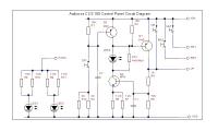
I drew out the circuit of the control pad

(Click on image for larger view)


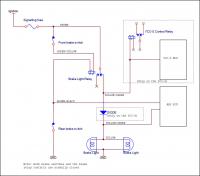
Not yet relevant to you until you get your 12V established, but the brake circuit only needs a relay if you have changed your conventional bulbs to LEDs, provided you take the brake sense wire from the lamp wire. The brake circuit I drew out to clarify in my own mind how it worked.


This shows you MUST take the brake signal from the yellow wire under the seat on an AE (AS) .


I would also add that the lamp will give a better ground than a relay, its cold resistance is much lower than a relay coil's.

(My installation posting, and my whole take)

 
The need for a relay is in part determined by the specifics of the individual servo mechanism. Some are a lot more sensitive to leakage than others. It is a trial-and-error problem and some unmodified bikes will require a relay, others will not - some will work when installed without a relay, then will fail, necessitating the installation of a relay after the fact. In my installation I took no chances and installed the relay - in the end I needed one, if for no other reason than to drive my modulated auxiliary brake lighting. Relays are cheap. I suggest installing one to eliminate the possible future need to troubleshoot the installation because of drifting in the op-amps in the servo due to aging.

 
The need for a relay is in part determined by the specifics of the individual servo mechanism. Some are a lot more sensitive to leakage than others. It is a trial-and-error problem and some unmodified bikes will require a relay, others will not - some will work when installed without a relay, then will fail, necessitating the installation of a relay after the fact. In my installation I took no chances and installed the relay - in the end I needed one, if for no other reason than to drive my modulated auxiliary brake lighting. Relays are cheap. I suggest installing one to eliminate the possible future need to troubleshoot the installation because of drifting in the op-amps in the servo due to aging.

 
Just to chime in with a more simple pre-check, I wanted to make sure you were actually trying it on the road and that's when you experience it not engaging. If you're trying to do it on the centerstand or something, the engine needs to be under load (otherwise the RPMs will rise up and the CCS100 will disengage).

 
I would also add that the lamp will give a better ground than a relay, its cold resistance is much lower than a relay coil's.
Just noticed the above. It is incorrect;

The brake input to the CCS-100 is wired to the relay contacts and NOT to the coil - the normally open contacts of the installed relay provides a hard connection for the brake input to ground - that's why you install a relay in the first place.

The relay coil is wired across the brake light power, the N.O. contacts go to the brake input on the CCS and ground respectively.

 
He wasn't to the point of a road test, yet. He saw that he couldn't even turn the unit on, because the brown wire wouldn't stay at 12 volts. He's also said that the black wire from the control pad wasn't grounded, which is exactly the reason for that. Perhaps he thought that black wire was redundant to the black wire from the servo, but it's not. The keypad must be grounded or its latch circuit won't work, exactly what he's experienceing.

Let's get the thing actually powered up before we try to troubleshoot its operation. :)
Let you all know in an hour. It is in the shop right now and the first thing I will do is give the brown wire the 12 volts it is looking for.

 
ALL FIXED NOW!!!

Tied the brown and red wires together, continued on with the brown wire to a new single pole, double throw momentary micro-switch which is conveniently integrated in the housing of the shift switch. Looks real pro. Went on it's maiden voyage and it works great. The added bonus is that the switch is a lot easier to operate than the pad with your gloves on.

Thanks to all that helped me out. Teamwork makes it work.

Rob

 
Congrats on getting it done. This farkle was way beyond my skill level but my brother in law is an electronics guru and hooked it all up for me. Once working, the AVCC100 is such a sweet addition to the bike! Mine's got almost 30K miles since the install and still works flawlessly. Well worth the headache.

 
Top