Cruise Control Not Working

Yamaha FJR Motorcycle Forum

Help Support Yamaha FJR Motorcycle Forum:

This site may earn a commission from merchant affiliate links, including eBay, Amazon, and others.
geez guys, I'm going now to take some advil and the rest of my meds :dribble:

this is why I became a mechanical engineer: I can throw the ball, grab the pendulum, spin the gears, shoot the gun, and take the piston out of the engine and hold it and look at it.

dem electrons are a mystery... :blink:

 
Yeah, I'm not any brighter than Alan on a Sunday morning. Since they're in parallel the relay is not carrying the load, and my cereal-mushed brain was looking at them in series. But a properly placed diode takes care of what you describe, I think, and keeps the lights on the switched circuit off of the relay.

Hmmm, now you got me thinking, which is never a good thing!!!

I wonder if I were to to simply place a diode in series with the purple wire to the CCS-100, would this prevent the purple wire from seeing 8V when the brake lights are off, and allow the CC to engage without using either the relay or the auxiliary lamps??? Would certainly be a much easier solution than I came up with.

Now that I am a certified expert at removing the rear tupperware to gain access to all the brake light wiring, I might just give that a try sometime.
A diode won't do it because the purple wire has to hauled to a solid ground. The .7 volt diode drop is too much, which is why *we* need a relay.

OTOH I have no clue why it is that if you wire to brake switch (on a Concours 1000) with tungsten filaments it works, but add a LED package and it doesn't. So we install a relay.

I have a friend with an older Mercedes of some sort and he tells me that when his brake lights go out that if he doesn't use an Osram branded bulb as a replacement his cruise control won't work - won't take a GE or any other. It MUST be an Osram.

You have to wonder how they manage to do that.

 
Last edited by a moderator:
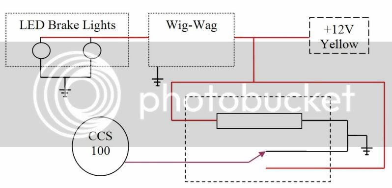
Would something like this work?

- With the brakes off, the CCS-100 would see Ground (0V) on the Purple wire. It expects to see Ground via the bulb filaments, so this direct connection to Ground may confuse it.

- With the brakes activated, the CCS-100 would see 12V on the Purple wire. This is as expected.

Of course, this calls for a 5-terminal relay rather than the more common 4-terminal style (SPDT versus SPST).

ccs100-wigwag.jpg


Yes, I know, my drawing skills suck. :)

 
That'll do it . . . you don't even need the positive connection to the normally open contact because there's an internal pullup resistor in the CCS-100 . . . if the lead is floating the cruise will disengage and won't allow you to set (assuming you leave the switches in their default positions).

 
One could just install a resistor in parallel with the Wig Wag and AudioVox inputs from the brake light switches. One end of the resistor would be connected in parallel with the Wig Wag input wire and AudioVox purple wire. The other end of the resistor would be connected to ground.

This would be a "pull-down" resistor. Pull-downs are used to hold the input to a zero value when no other component is driving the input. In the typical AudioVox circuit the brake light lamps function as pull-down resistors. They are low resistance (7 ohms each or 3.5 ohms parallel) paths to ground.

--------

Get a 470 ohm 1 watt resistor and connect it in the circuit.

For 14 volts the power consumed by a 470 ohm would be 0.42 watts. Of course only when the brakes are applied.

The resistor would provide a grounding path for the AudioVox purple wire when the brakes aren't applied.

Don't think the resistor would have any negative effect on the Wig Wag.

 
Last edited by a moderator:
bramfrank: thanks, I kinda sorta thought the connection to the positive side wasn't needed, but wasn't sure. It would be easy to eliminate it, of course.

Constant Mesh: I like the idea of using a pull-down resistor, but wasn't at all sure what value it should be. I was thinking something in the range of 10k to 20k ohms, but you say 470 @ 1 watt should work. Won't that warm up significantly while you're sitting at a stop light with the brakes applied?

 
The 470 ohm resistor size is totally arbitrary. I chose it after thinking about relay coils. I'm using three control relays on my AudioVox setup. They have 160 ohm coils.

The resistor will consume 0.42 watts whenever the brakes are applied. Not all that much and less than a relay coil. And, of course, the vast majority of the time it's consuming 0 watts so heat's not really a big issue.

 
I wouldn't bother - you'd think the bulbs alone would do the job, given that they suck some 30 watts but for some reason when you have something IN ADDITION to the normal load it seems to mess up.

A relay is cheap.

 
Top