cruise control

Yamaha FJR Motorcycle Forum

Help Support Yamaha FJR Motorcycle Forum:

This site may earn a commission from merchant affiliate links, including eBay, Amazon, and others.
Unfortunately the Audiovox does not have the diagnostic capability of the McCruise, nor does it have the great support of the McCruise. There are 2 areas I would look at. One has already been mentioned and that is voltage on the brake light wire that will disconnect the cruise control. There are many posts about adding a relay to keep that wire grounded until the brake light is activated. It's true, do it. The second is sticky solenoid plungers. Disassemble each one carefully and clean them with alcohol. Do NOT use acetone or brake cleaner. I disagree with the people that say the cruise will shut down if the cable is too slack. I wish it did. Mine had a lot of slack and sometimes would not engage until a mile or two after I pressed the SET button. Of course we know NOTHING about the Audiovox firmware and any revisions that it may have. Maybe some shutdown from too much slack and others don't. I also question the reliability of using the ignition coil as the vehicle speed source. The McCruise uses a sensor picking up a magnetic field from 6 magnets inserted into the 6 bolts holding the disc brake rotor. I would like to try that but I have not found any 6mm diameter cylindrical magnets yet. I also tried connecting the rear wheel ABS hall effect sensor to the Vehicle Speed Sensor line of the cruise control but that did not work. The connection had no effect on the ABS. The output of that sensor swings from .5 volts to 1.5 IIRC. It also has a frequencyof pulses per mile higher than the Audiovox switch settings call for. Currently I have all 4 cylinders connected to the speed control with a check valve for each cylinder. I have a vacuum reservoir but it is currently disconnected and I notice no difference. The McCruise does not use a vacuum reservoir. I hope that something in this post provides some help for you. My next cruise control addition will be with the Rostra unit and using a speed sensor signal, but that will be on a different bike. I am satisfied with my Audiovox but it does have some quirks and definitely is lacking compared to the factory cruise.

 
The Audiovox kits come with magnets and a pickup if you want to use that, but they're meant for tying around an drive axle or drive shaft, and a bit difficult to set up on the Feej. besides, they're no more reliable than using the tach. The only difference is you get road speed instead of engine speed, which means you could resume in 4th gear instead of 5th and still get to your set speed instead of your set RPM.

That "mile or two after pressing the set button" sound hinky, for sure! Of course, that's only nine seconds or so at 400mph, so if you're setting it at that speed, I don't really see the problem..... :)

The thing that comes to mind on that for me is not letting go of the throttle when you set the cruise. If you hit the set button but continue to hold the throttle, not letting the speed drop, the cruise won't engage because it has no need to add throttle. The set speed is already maintained, by your hand on the throttle. It doesn't kick in because you hit the "set" button, it kicks in when your speed drops below its threshhold, whatever that may be. It won't take over until you let go and the speed drops far enough to make the unit want to take over. it may be an incorrect sensitivity setting, allowing the speed to drop too far before it adds throttle to recover.

That said, mine is pretty quick to cut in, but I generally set it by going above the speed I want, backing off, and hitting the button as I pass the speed I want. For some reason that seems to set more accurately. I do know for a fact, though, that if the bead chain got too much slack, which happens if the cable clamp holding the CC cable in place gets loose or twists down, then my CC would not engage.

 
Well I am really no better off today that I was last week. I spent some of my weekend working on this. I was not able to spend hours and hours on it, but I spent enough time to do a few things. I purchased a vacuum pressure gauge and checked the vacuum back at the hoses by the servo unit and all was within spec. I cannot recall exactly now but after the bike was warmed up it was around 25 at idle. I do not remember if it was (inches, pounds, etc), but it was what the information in one of our other threads told me it was to be.

I checked a few basic electrical connections to the unit but did only a quick electrical check by using the LED. The light blinked slow at idle, sped up as the RPM's increased and it went off when the brake was activated, and back on when released. It seemed that those two things were working. To ensure that that the linkage was right and there was not too much or too little slack in the chain I actually reinstalled the whole servo unit. I did not have to reinstall the connector that is anchored to the tang but from there up I reinstalled it using great care to make sure that the unit was not pinched or rubbed on anything as the chain moved. I actually did this three times over the weekend. Putting the tank and seat on and taking it for a spin. It never worked!!!

The newest wrinkle to the whole thing that may shed some light is that when I took it out for the second test ride it was cold and I was not really dressed correctly so I tuned on my heated grips. As I cruised back through my neighborhood at low speed my dash went out, ABS light was on and the bike was running real rough. I barely made it into the garage before it just died. Had to charge the battery to get it back into neutral (AE model) to push it back to where I wanted it. This had me scared that I really messed something up in the wiring like a pinch had rubbed through and it was all shorting out. I took the tank off AGAIN and checked and there were no issues with any wires or anything so I left the charger on (C-TEK charger). The light on the charger turned green, I rode it again but without the hand warmers and all was just fine. I returned home, turned it off, restarted it and again as a test and all was well. I put the charger back on it anyway and went in as I was very frustrated to say the least. Last week when I rode it I had to get a jump start in a parking lot as the battery failed me. I am wondering if the battery is a part of my problem with the cruise control. Like I said before.. the cruise was working last year when I put it up and now it is not, I did nothing to bike over the winter to change anything. I did have it in the charger over the winter but perhaps my electrical problem is from the source of the electricity and not the flow or path of the electricity. I have a FUSEBOX under my seat for accessories. It is fed straight from the battery. I only have a few LED lights, and not the brake lights, as well as the Cruise Control running off of this. The LED accent lights were running off of it before when the unit was working.

I know that was a lot to say, but I have noticed that there has not been a lot of traffic on the forum here lately, so I will take advantage of that and help myself to you guys and your input.

 
Do you have a voltmeter on the bike? Running, with no extra high-load accessories like the heated grips, you should see 14, 14.1, 14.2 volts at the battery. If it gets down into the low 13s or less when you turn stuff on, then you'll be draining the battery as you ride rather than charging it.

Some of that also sounds suspiciously like the ground spider issue. Even if it only happened with the grip warmers, that may be the load that trips it up. Have you had that recall done?

 
I have had the ground spider recall done. Having an AE I was left stranded because of it. I could not get it in or out of gear. It really caused a problem for the mechanic because the problem wouldn't allow him to open the "glove box" that can only be opened with the key on.

Anyway, I do not have a voltmeter on the bike so I do not have any idea on how much I am pulling. I have a C-TEK harness wired in for charging that I could plug my C-TEK accessory plug into it and plug a voltmeter into that I guess. Do they make a voltmeter that would plug into a cigarette lighter outlet? I can hard wire one in I guess but just never felt the need to , until now I guess, to have one permanently mounted on the bike.

 
slight highjack-apologies

I installed a Rosta electronic cruise one year ago and have been fighting with the Gdm thing ever since. I used good info from the forum as regards tack and speed signal connections to the ECM harness and switch settings. It works perfectly except for random drop outs-sometimes after 15-20 minutes, sometimes after 15-20 seconds. Tried everything-brake relay, ground brake wire to eliminate any brake problem, multiple switch settings, a signal divider altho Ionbeam's estimate of @ 33K pulses / mile seemed right and should be handled by the CC. Always random dropouts. I was ready to try a magnetic signal generator when in a flash of brilliance I reread the manual and saw that the dark blue tack wire could be left unused and grounded but the over rev safety would be lost. I did that and great joy, finally no dropouts ever. Now works as smooth as the cruise in my Charger R/T. Don't understand why but I'll take it...

 
I did some testing over he weekend and I do not have "0" Volts on the CC brake wire. After speaking with a guy at the factory he says to check the unit by just connecting the wire directly to the ground lug on the battery but I would have to disengage the unit by hitting off as opposed to using the brakes. This makes me a bit nervous and would rather try another way.

My kit came with a coil that I can wire in to ensure a "good ground" but I am not too sure about the wiring. There is less info on how to install this then there is for the CC itself. Does anyone have any more help they can give. It seems that it my issue has been narrowed down to this so we are about done with this.

 
I did some testing over he weekend and I do not have "0" Volts on the CC brake wire. After speaking with a guy at the factory he says to check the unit by just connecting the wire directly to the ground lug on the battery but I would have to disengage the unit by hitting off as opposed to using the brakes. This makes me a bit nervous and would rather try another way.My kit came with a coil that I can wire in to ensure a "good ground" but I am not too sure about the wiring. There is less info on how to install this then there is for the CC itself. Does anyone have any more help they can give. It seems that it my issue has been narrowed down to this so we are about done with this.
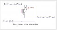
Best way for your relay is to be wired so that the CC's brake wire (purple for the Audiovox) is switched to ground when the brake is not energised, and to the 12 volts going to the brake lights when the brakes are on.

The diagram below shows the wiring. Note the wire I've marked "Yellow" is Yellow/Green on the FJR1300A, it's Yellow on the YCC-S variant.

(Click on image for larger view)


I can't help you with which terminal is which on your relay.

 
Last edited by a moderator:
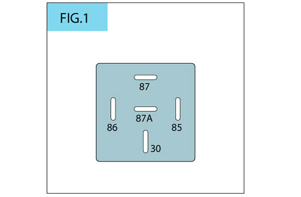
An automotive relay will have the terminals numbered like this:

fig_1c10.jpg


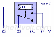
This is how the relay will look when OFF, like shown in mcatrophy's post.

relaytext2b.gif


Regardless of the relay's physical pin positions, the numbers will always electrically match Figure 2.

 
Last edited by a moderator:
Thank you for the line drawing. I will have the electricians here help me understand it better. I am good at the nuts and bolts stuff as I am a journeyman carpenter, I do understand a lot of the electrical but sometimes it gets me a little confused. I will do what I can.

 
as stated, the brake wire needs to "see" ground when the brakes are off and lose ground when brakes are applied.. it does not, however need to have 12 v when the brakes are applied..

 
It does need volts with brakes, just not necessarily all 12 of them, and it doesn't specifically need to be grounded with no brakes, it just needs very very very few volts. Grounding it is an easy way to ensure very very very few volts, but a dead-end wire also has very very very few volts. On the Gen-II, with the relay in the brake circuit that they have, that line isn't always such a dead end for some reason. It will have a low number of volts, but not close enough to zero to satisfy the CC box, as our esteemed OP has discovered.

 
Last edited by a moderator:
Now I am getting very frustrated. This thing is kicking my but. I oversee the construction of hospitals, schools, banks etc. and I can't even install a friggin CC on my scooter.

I am really laying myself out there and showing my vulnerability in this area, but does anyone know which wires of the coil go to which wires on the bike. The line drawings/schematics are not simple enough for me. The cruise came from Murph and the coil has 5 wires coming from it. It has two lighter gauge wires (white and black) and three heavier wires that are a heavier gauge (orange, blue, red).

I have tied different combinations but without success. The drawings in previous posts call out what the wires do and how much power they will or should carry, but I cannot figure out where to attach to get that power. I feel like the guy in one of the posts I've read that said he was ready to start the bike on fire and that is about where I am now. If it would have never worked before I may not be so frustrated. Please help if you can. I cannot even take this to a scooter shop as no one wants anything to do with an after market *******ized CC like this. You guys are all I have.

I cannot figure out how to get a picture on this forum either or I would send a pic of what my coil looks like and a pic of the wires under the seat that I have tapped into. I can cut and paste blue prints and change orders all day long but I can't get it to work for me here.

 
The Murph’s relay is numbered just like the relay shown in post #29. In Figure 1, the pin layout for the relay is shown with the corresponding pin number. The way the pins are laid out horizontal/vertical there should be no confusion. I would expect the bottom of Murph’s relay to have the pin numbers embossed right next to the pins but some rare times the relay manufacturer does not do this, if this is the case refer to Figure 1.

Wiring the relay coil: The coil is not polarized, ground and 12 VDC can go to either pin (follow the color code in the pigtail harness, I don’t know which color wires go to which pin in Murph’s pigtail). Wire pin 85 to any ground which is always ground – the frame, battery ground or power distribution ground. Connect pin 86 to the yellow/green wire in the rear brake light connector, this wire will be 12 VDC only when the brake is pressed.

Wiring the relay contacts: Connect the AVCC purple wire to pin 30 of the relay. Connect pin 87a to any ground which is always ground. Connect pin 87 to any 12VDC which is always 12 volts when the key is turned ON. The solid brown wire in the brake light connector would be one 12 VDC source.

relay-pigtail.jpg


When the brake is NOT on there is no power to the coil of the relay, so pin 30 of the relay (connected to the Purple wire of the AVCC) is switched to pin 87a which is ground all the time which makes the AVCC happy and allows it to set speed.

When the brake is ON the yellow/green wire supplies power to the coil of the relay and energizes the relay. This causes the relay to switch, connecting pin 30 (AVCC Purple wire) to pin 87 which is 12 VDC, this makes the AVCC stop speed regulation.

 
Last edited by a moderator:
It does need volts with brakes, just not necessarily all 12 of them, and it doesn't specifically need to be grounded with no brakes, it just needs very very very few volts. Grounding it is an easy way to ensure very very very few volts, but a dead-end wire also has very very very few volts. On the Gen-II, with the relay in the brake circuit that they have, that line isn't always such a dead end for some reason. It will have a low number of volts, but not close enough to zero to satisfy the CC box, as our esteemed OP has discovered.
hmm-mine is hooked up so that the purple brake wire has ground thru the closed relay [brakes off].......with brakes on the pulldown coil opens the contacts and the CC brake wire has zilch...can't see where any current could come from..

and-dumb ques here-I know 67DLA has a different kind of CC but why use the coil for speed signal...why not take PPM off the ECM connector [forgot which wire]

actually the signal from the ABS trigger wheel... meebee his CC can't handle that high a signal-@33,000 PPM?

 
...
hmm-mine is hooked up so that the purple brake wire has ground thru the closed relay [brakes off].......with brakes on the pulldown coil opens the contacts and the CC brake wire has zilch...can't see where any current could come from.....
The cruise controller feeds a small current onto that wire to see if it's pulled hard down by the brake lamp-bulbs, as does the bike's ABS computer (and the YCC-S computer if relevant).

 
Last edited by a moderator:
It is working!!!! I was still very discouraged as it still was not checking out at "0" volts, but I went ahead and made good positive connections for all the wires for the relay, and put the bike back together and thought I would pick this up again in the spring. After I did all the electrical stuff I decided to check the parts in the servo unit. I wasn't sure what all there was to do to so I just started dissecting. It appears there are little silver needle valve looking parts in each of the yellow coils. I pulled them out and wiped them off and put it all back together. I decided to take the bike for one more ride. I hit the CC on button and then the set button and it worked. I kind of let out a little cheer as I was riding.

I must have looked a little funny as it was 33 degree out and I was only wearing my Carhart coat and a stocking cap. I had a big grin on my face and kind of chuckling as was feeling so good that it was working. I cannot say definitively which step it was that caused it to start working but I am leaning toward the cleaning of the needle valves. The relay may help it operate better as it is getting the proper grounding now when before it must have been borderline. Since it was once working, and then not, the only thing that could have actually went bad is a moving part...the needle valves. I looked at them early on as suggested but didn't realize that they came out like they do, but now that I know it will be the first thing I will check if it shuts down again. I will test again later in the week when it is a whole 10 degrees warmer and I am dressed appropriately.

Thanks for all the help!!!! I would have never been able to do it without this resource.

 
...It appears there are little silver needle valve looking parts in each of the yellow coils. I pulled them out and wiped them off and put it all back together...the only thing that could have actually went bad is a moving part...the needle valves...
Glad you got it working. This is what I was talking about in post #13 where I showed the solenoids.


Latest posts

Top