Do I Have a Spider Problem?

Yamaha FJR Motorcycle Forum

Help Support Yamaha FJR Motorcycle Forum:

This site may earn a commission from merchant affiliate links, including eBay, Amazon, and others.
...removing the upper front dash panels C and D (I think that's the names, I've lost my owners manual!)...
Nuttin' to do with spiders, but you can go to the Yamaha web site and download the owners manual for freebie.
Thanks ionbeam, I've done this but it seem like it's locked for print. That is, printing is disabled. I want to be able to print pages to take out to the garage with me. Any other recourse that you know of?Regards,

Rich

get an OLD lap top?
 
Since this is the OP and their thread:

Thanks ionbeam, I've done this but it seem like it's locked for print. That is, printing is disabled. I want to be able to print pages to take out to the garage with me. Any other recourse that you know of?...
Hmm, I just went to Yamaha's web site and got the '07 owners manual, it let me print the whole manual as well as selected individual pages. Dunno why it doesn't work for you.

If you are still having problems printing: * Select PRINT *In the PRINT drop down box click the arrow on the NAME box *now select Microsoft XPS Document Writer from the list *instead of printing to a printer it will print to a Word XPS document that you save to your computer *this document can be printed as if it were a Word document.

At least this is how it works on a computer (as opposed to tablet or phone) running Micro **** software.

And, if all else fails, send me an email address and I'll send ya a printable copy of the manual.

 
Last edited by a moderator:
This thread will be useful for removing plastics!!!

https://www.fjrforum.com/forum//index.php/topic/116788-gen-ii-plastic-and-cowling-removal/?hl=plastic

Keep in mind that a "spider" may look perfectly good from the outside and still be a problem. I had one (S6, I think) that looked SLIGHTLY darkened on part of the outside. When I removed the 6-legged connector from the socket, one of the legs appeared to be a bit heat-tarnished but otherwise OK - definitely not burned. I cleaned it up with some fine emery paper followed by isopropyl alcohol. Reassembled it using a bit of silicone grease. That lasted about two weeks until I had to proceed with the major surgery (cut, strip and solder).

 
I had an S7 failure and so I removed the entire front cowl assembly to gain access. Much easier to work on it when it's laying upside down on the workbench! There is a write up on removing the whole front assy somewhere on this forum, but regretably I did not bookmark it. It's not as hard as it sounds.

As far as printing anything that doesn't want to print, I've installed a great shareware program called ScreenPrint32 that turns your Print Screen button on your keyboard into an actual Print Screen function. There's lots of configuration options, but mine is set to print exactly what's display on the computer monitor.

 
This thread will be useful for removing plastics!!!
https://www.fjrforum.com/forum//index.php/topic/116788-gen-ii-plastic-and-cowling-removal/?hl=plastic

Keep in mind that a "spider" may look perfectly good from the outside and still be a problem. I had one (S6, I think) that looked SLIGHTLY darkened on part of the outside. When I removed the 6-legged connector from the socket, one of the legs appeared to be a bit heat-tarnished but otherwise OK - definitely not burned. I cleaned it up with some fine emery paper followed by isopropyl alcohol. Reassembled it using a bit of silicone grease. That lasted about two weeks until I had to proceed with the major surgery (cut, strip and solder).
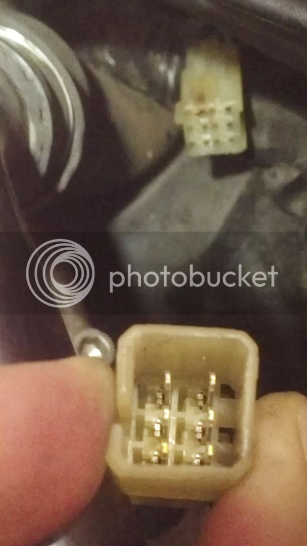
Thanks Ross for the link. When I inspected the two spiders so far, I too removed the 6-legged connector from the socket. They looked perfect as did the connectors. below is a photo of the S6 connector

IMG_20160824_175945_zpshyaxrnix.jpg


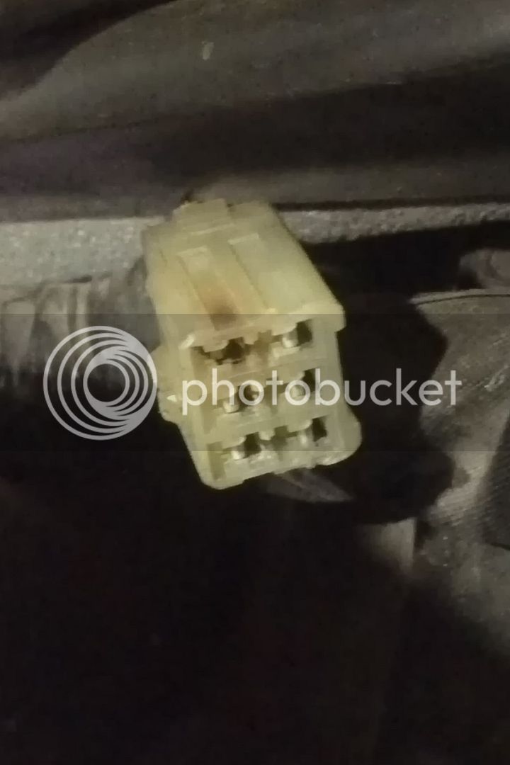
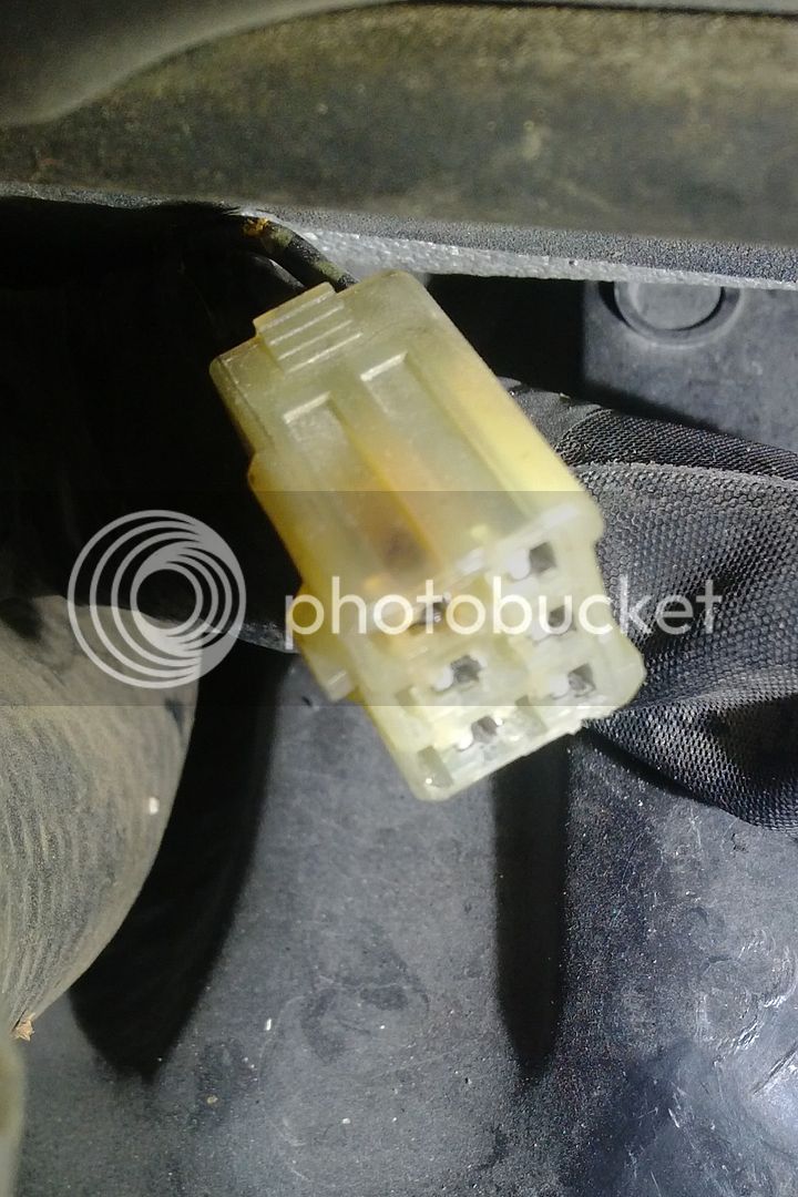
..and here's a photo of the "vibrzn/rosskean" 6 pin connector

IMG_20160825_080206_zpsewx1cfyl.jpg


Is the any chance that a flaky an ignition switch could be responsible?

 
I was wondering about that but did not think it was likely based upon your descriptions. Can you get odd stuff to happen by wiggling the key after it is switched on. (lights/meter needle sweeps/indicators etc.?)

 
Here is a list of symptoms:
Ignition in on position, not attempting to start bike.

1) Running lights ok, no abnormal activity

2) Brake activated (either hand or foot) -> brake lights work normally and no abnormal activity

3) Raise/lower windscreen -> results in very slow movement AND the bright light indicator lights up.

4) Hit horn -> no horn sounds but both turn signals light AND the bright light indicator light up.

5) Turn on either turn signal -> the turn signal will flash AND the bright light indicator lights up in sync. with the turn signal

6) Activate flasher -> turn signal will flash AND the bright light indicator lights up in sync. with the turn signals

Ignition in on position and attemp to start bike

1)In gear, kickstand up and clutch pulled in -> pushing start button does nothing except illimunate the bright light indicator.

2)In neutral, kickstand either up or down, clutch either pulled in or not -> pushing start button does nothing except illimunate the bright light indicator.
...When I inspected the two spiders so far, I too removed the 6-legged connector from the socket. They looked perfect as did the connectors. below is a photo of the S6 connector
..and here's a photo of the "vibrzn/rosskean" 6 pin connector ...

Is the any chance that a flaky an ignition switch could be responsible?
There are too many independent items not working for it to be the ignition switch, IMO. Usually the kind of oddball light combinations are the result of a bad ground. I do see that a lot of the problem items share a common ground at the meter assembly. This ground comes through non-spider connector #31 which is a rectangular 6 pin connector going in part to the meter assembly. There are a number of signal wires which pass through the connector but it is the single ground wire that is of interest. When the odd dash lights are happening (force the condition to occur), if the temperature gauge reads wrong then this connector is very likely your problem. There is also a signal wire to the starter cut-off relay which passes through connector #31 which would inhibit starting.

If the temp gauge reads correctly then the electrical issues are back to looking at the ground spiders.

Edit: Ross managed to say a similar conclusion using far fewer words
smile.png


Last edited by a moderator:
There are too many independent items not working for it to be the ignition switch, IMO. Usually the kind of oddball light combinations are the result of a bad ground. I do see that a lot of the problem items share a common ground at the meter assembly. This ground comes through non-spider connector #31 which is a rectangular 6 pin connector going in part to the meter assembly. There are a number of signal wires which pass through the connector but it is the single ground wire that is of interest. When the odd dash lights are happening (force the condition to occur), if the temperature gauge reads wrong then this connector is very likely your problem. There is also a signal wire to the starter cut-off relay which passes through connector #31 which would inhibit starting.

If the temp gauge reads correctly then the electrical issues are back to looking at the ground spiders.

Edit: Ross managed to say a similar conclusion using far fewer words
smile.png
Thanks ionbeam and RossKean.

First to answer RossKean.. occasionally when I turn on the ignition and immediately see the high beam indicator on and then try to start via the start button(which it doesn't), I've been able to start by pushing down on the key. Unfortunately I cannot completely replicate this. It may be coincidental. Sometimes when it start up, the lights are off for 20-30 seconds and the hobeam indicator is on. Then suddenly the lights come on and the hibeam indicator goes off!! This is driving me crazy.

Ionbeam, I'm assuming connector 31 is the 6 pin connector in the picture I posted. This is the one that RossKean and vibrzn posted (thus I gave it that moniker). I don't have a service manual. Am I correct about this being connector 31? Which is the ground wire in that connector?

By the way, after I read your post I went to the garage and tried to start. Turn key and see high beam on...hit start button and nothing..push hard on key it started. I let it warm a bit until I got 3 bars on the temp. Turn it off and could not restart (the hibeam indicator again!). The temp gauge continues to work, however. IAftyer 10 minutes it still wouldn't start(again tried the push down key thing to no avail), but the temp was down to 2 bars.

I'm still pursuing S4, is it necessary to completely remove the tank, or can I gain access by just propping up the tank?

Thanks guys.

Regards.

 
I had an S7 failure and so I removed the entire front cowl assembly to gain access. Much easier to work on it when it's laying upside down on the workbench! There is a write up on removing the whole front assy somewhere on this forum, but regretably I did not bookmark it. It's not as hard as it sounds.
As far as printing anything that doesn't want to print, I've installed a great shareware program called ScreenPrint32 that turns your Print Screen button on your keyboard into an actual Print Screen function. There's lots of configuration options, but mine is set to print exactly what's display on the computer monitor.
Thank you Harald. I'm putting off inspecting S7 and S8 until my other options are exhausted. I'm about to start S4. Also, thanks for your input regarding ScreenPrint32. I'll first try ionbeams suggestion then if need be request your ScreenPrint32 shareware.

Best regards,

Rich

 
Loosen the through bolt at the back of the tank, remove the two front Allen bolts, remove the trim and the S4 can be accessed by propping up the tank. You may want to remove the heat shield and T-bar. As well as the fuel pump and fuel gauge power connectors to the tank bottom.

 
Are the headlights on (may be quite dim) when you see the high beam indicator? Obviously they shouldn't be on until the engine has started.

The horn and windshield control share a ground return path.

I'd look at the headlight return path and its associated grounding junction. Headlights are high current which would stress the grounding junction.

 
Last edited by a moderator:
...I've been able to start by pushing down on the key...ionbeam, I'm assuming connector 31 is the 6 pin connector in the picture I posted...push hard on key it started...(again tried the push down key thing to no avail), but the temp was down to 2 bars...I'm still pursuing S4, is it necessary to completely remove the tank, or can I gain access by just propping up the tank?
Since the temp reads correctly the fault isn't the connector I was talking about, so never mind. It looks like you are still chasing ground spiders or a ground circuit someplace.

If you don't have a key issue right now, you will if you keep fiddling with the key
whistle.gif
The key switch is made in two halves, the upper mechanical tumbler part with a pin coming out the bottom (which shouldn't mechanically wiggle around) which rotates the bottom half with the electrical connections. Wiggling the key like you have been doing shouldn't make any difference to the bottom electrical half of the key.

If you have a volt meter we can take a lot of the guess work out of the diagnostics very quickly. The key switch and the spiders will be easy to diagnose once the tank is up and the connectors available for probing. If you haven't made headway by this weekend send me a PM via the Forum and I'll arrange a phone call if you can get a phone next to the bike with the tank up and a meter at hand. Unfortunately I won't be home until later Sunday 'cause I'll be out on the ocean from Sat until Sun morning but if our schedules meet at some point I'll try to help ya.

 
Last edited by a moderator:
Loosen the through bolt at the back of the tank, remove the two front Allen bolts, remove the trim and the S4 can be accessed by propping up the tank. You may want to remove the heat shield and T-bar. As well as the fuel pump and fuel gauge power connectors to the tank bottom.
Seems like nothings easy... I have the Helibars bridge and and tank flange won't clear the bridge. Maybe if I remove the pivot I can slide it back a bit I can then re-inser the hinge bolts and proceed? I bet FredW would know...he has a Helibars bridge too.

 
Update: I got the tank up in order to look at the spiders beneath. I was able to inspect S2 S3 and S5. I understand that S2 and S5 are not part of the high current "Neutral circuit", but hell, they are easy to access and inspect. For each I removed the 6-legged connector from the socket. They looked perfect as did the socket and wires, much like the photo of the S6 connector I posted above in reply #24.

Now, about S4.... it's had the recall fix done to it (apparently) as confirmed by Yamaha. I haven't been able to find a spider topic that shows a photo of S4 with the recall fix . I believe this is the S4 w/fix on my bike. It's located on the left hand side and forward of the cylinder head. It's the white plug with the fix cable(?) exiting to the right with the white tag around it ..or so I think.

IMG_20160825_175031_zpsa2oxxwhe.jpg


Can someone who's had the recall fix confirm?

In the morning I'll take the plug apart and inspect.

 
I have news... S4 has a burnt pin. You can't see it thru the recall harness connector. Pulling apart the connector revealed the damage.

Here's a pic of the assy.

S4%20img%206_zpsifhjv8mi.jpg


The next pic shows the connector disassembled. Note the female end with the discoloration (burn mark) on the top left. Closeups will follow

S4%20img%203_zpsakyelcq3.jpg


Next a closeup. Besides the burn, there's also what appears to be oxidation (white powdery stuff) in the female plug, although it doesn't show well in the pic. Don't see it on the male pins

S4%20img%204_zpsxjcycutm.jpg


Another closeup showing the damage.

S4%20img%202_zpsiwaypaed.jpg


The recall fix was performed on my bike in 2011 before I owned it. Since this is a failure on a recall, I'm going to pursue Yamaha customer service to repair it. I already have a ticket open with them, so I'll report my finding to them.

Comments?

 
Last edited by a moderator:
There's your smoking gun.
Or smoking connector as the case may be.

This is the first instance of a failed recall harness that I can remember seeing but it doesn't surprise me. You may or may not have any luck with Yamaha but it is worth a try. Perhaps they will replace the entire harness since the "patch" failed. This was supposed to be done if there was damage to the harness from a failed S4.

If no joy from Yamaha, I would just cut it off, solder the ends together and move on!

Glad you found it.

 
Last edited by a moderator:
Just for kicks, check the other end of the recall harness. Is it plugged in? Both places on that end? They reside in the space forward of the battery. You can access it by removing the black right side inner trim piece next to the right horn, in front of the radiator. It's 3 Philips head screws, 2 push pins and you're in -easy.

Brodie

🤔

 
Last edited by a moderator:
Yeah, it is interesting that the main ground wire overheated if the harness is in place. Each of the pins should go to ground via the recall harness, so the main ground wire shouldn't carry all that much (if any) current. Maybe the pin was already scorched when they installed the harness and just didn't want to replace the entire bike wiring harness? Or maybe the other end is disconnected like you mention?

 
Last edited by a moderator:
Top