Front end lift

Yamaha FJR Motorcycle Forum

Help Support Yamaha FJR Motorcycle Forum:

This site may earn a commission from merchant affiliate links, including eBay, Amazon, and others.

Lee B.

Well-known member
Joined
Jun 6, 2008
Messages
441
Reaction score
0
Location
Leawood, KS
I really like the recent work done on a stainless steel front end lift. I also looked at some of the commercial varieties and considered purchasing one at about $90. Not a bad price. I have limited tools and limited skills, can't weld, don't have that equipment so I considered what I could use to build my own.

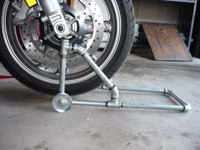
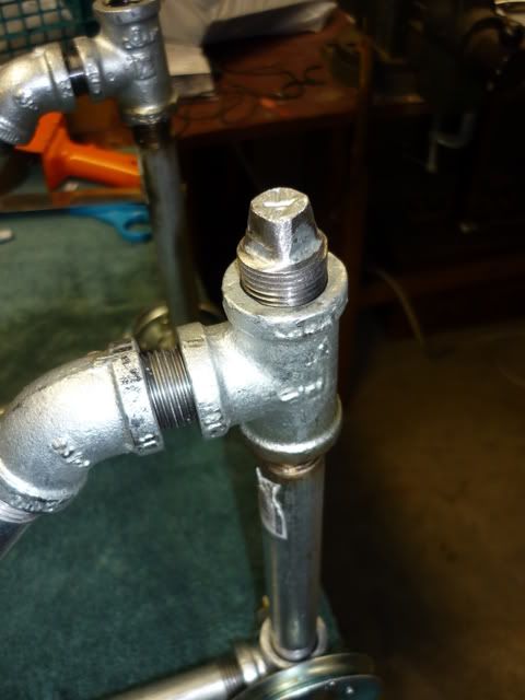
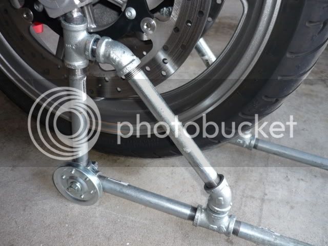
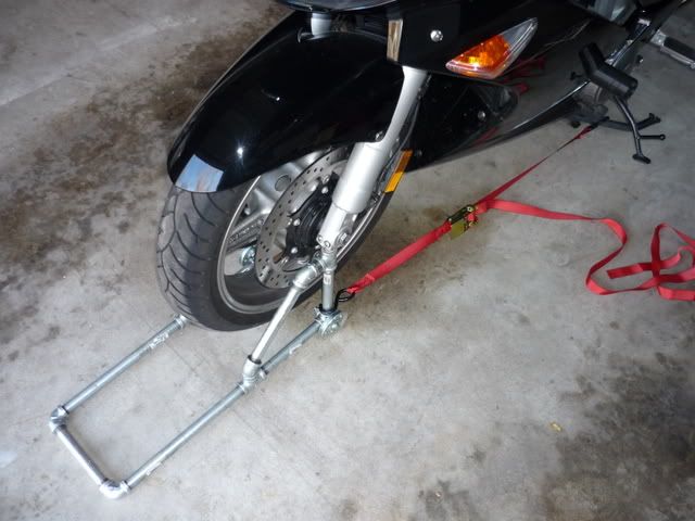
I decided on 1/2" galvanized pipe. Realtively cheap, easy to assemble tool-wise, accessible, probably strong enough for the job. I got out pad and pencil and started sketching this out and measuring the bike, deciding how to go about it. Then I went shopping for:

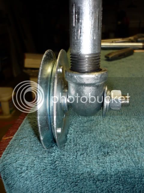
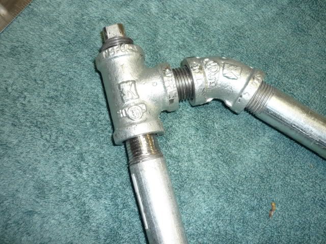
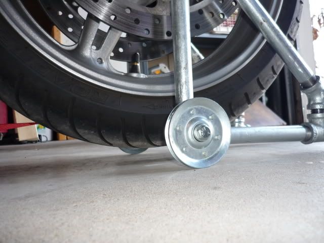
4 90 deg elbows; 4 45 deg elbows; 4 Ts; 4 close nipples; 2 caps; 5 pcs 7" gal pipe; 2 pcs 12" gal pipe; 2 pcs 8" gal pipe; 1 set of two 3" steel ball bearing rollers for a garage door; bolts/nuts/washers for the rollers to use as axles for the rollers/wheels.

I just found out I need to do more research on how to post pictures. I thought I was following the instructions to embed photobucket images but got a message that the administrator doesnt allow from that site. I'll go ahead and get this out and then will come back with photos and more instructions once I do some reading. I have posted photos before and thought I was doing the right stuff but I must be missing something. Off to read the instructions again...

 
Here is the finished product:

P1000207.jpg


Here is the finished product:
P1000207.jpg
Okay, got the picture to work. It works for me when I straight cut/paste into the page and not use the insert image button.

Anyway, this lift works well. It lifts the tire about 1/2" off the ground and the rear tire is still about 1" off the ground. I figure I could use a reducer under the cap that goes into the fork but that might lift it too high. So, I'll probably slip some 3/4" plywood under on each side and roll it up on that to get a little more height.

I'd like to hear back from anyone that has used a lift on how much off the groud the tire has to be to remove the wheel. I read that the fender has to be removed and it looks like the wheel will clear the brakes by simply moving forward, not a whole lot down.

If there is interest on more detailed instructions or hints just give a reply here and I'll tell you what you need to know to duplicate this. The biggest surprise was the cost of pipe. It has been a long time since I had to buy any of this for a home project. The total for all parts for this lift was about $60.

 
Pretty slick Lee.

I'm assuming the bike is on the center stand. Do you think you could remove both wheels at the same time with this setup?

Maybe use the board/jack under the headers for a safety net.

 
Pretty slick Lee.I'm assuming the bike is on the center stand. Do you think you could remove both wheels at the same time with this setup?

Maybe use the board/jack under the headers for a safety net.
Thanks!

both tires are off the ground so I thnk maybe both wheels couuld be removed at the same time if 1" clearance on rear adn 1/2" clearance on front is enough. I've not done it yet....just 3700 miles on the bike.

Yes the bike is on the center stand. I tend to be extra cautious and strapped between the c-stand and the back upright of the front end stand I built. Keeps the front end stand from moving forward and the c-stand from moving back. I also am considering a 3-4' lenth of pipe to run under the front lift wheels perpendicular. I'd have eye bolts o nthe ends and use that as a tie down for the front forks for more side to side stability. I have no idea how much wrestling is needed to remove the wheels so that sort of stability might not be needed.

 
That's using your noodle! Well done! Are your fittings threaded or slip-fit & brazed?
Nice job.
Well, sort of both. All the fittings came threaded. As you know you can't close a circle unless one joint is reverse threaded. What I did to close the triangle part is to grind off 1/2" of the end threads on the straight pipe going into the T that is right under the fork. I just tested this this morning adn now that I know it works I'll use solder or JB to secure the pipe into that T. Right now it is up into the T about 1/2" and a pretty tight fit but this will make it more secure. I figured with the downward wt of the bike that was the best place in the triangle to not have a threaded connection.

 
I like that! Nice work, you were limited to how to build the stand but it looks like YOU aren't limited in brain power!!

Props to you! :thumbsupsmileyanim:

 
As you know you can't close a circle unless one joint is reverse threaded.
Yeah, for a while there I was going "heyyy, wait a minute..." So how are the wheels attached? And what are they? And do they actually roll?

 
Nice work, I was thinking about building one myself. What did you use to go under the forks? And how did you attach wheels did you drill through pipe? More pics would be nice.

 
Nice work, I was thinking about building one myself. What did you use to go under the forks? And how did you attach wheels did you drill through pipe? More pics would be nice.
The parts list I posted included two 1/2" gal caps. These screw into the Ts you can see just under the forks. The caps have a little square post sticking out the top. I used my grinder to slightly round off the square edges and they fit up into the forks high enough to hold.

I used a 3/8" bit to drill the holes in the bottom 90 degree elbows. I had each side built but not attached together. Laid them down flat adn used a file to slightly flatten the elbow. then I measured 3/4" up and over to center a spot for the 3/8" hole. I used a punch, then a 1/8" bit to start then switched to the 3/8". I just have a drill, not a drill press so I asked a buddy to finish the holes on through to the other side for me. Once that was done it was easy to use the bolts for axles for the wheels.

what sort of pix would you like and I'll try to provide.

Lee

 
As you know you can't close a circle unless one joint is reverse threaded.
Yeah, for a while there I was going "heyyy, wait a minute..." So how are the wheels attached? And what are they? And do they actually roll?
They are the garage door hardware listed in the post above. They are each 3" pulley wheels. they have steel ball bearings so yes they do roll. I drilled holes, used the wheels on the outside, used a bolt through each to create an axle and then used a flat and a split washer and a nut.

 
[

Nice work, I was thinking about building one myself. What did you use to go under the forks? And how did you attach wheels did you drill through pipe? More pics would be nice.
The parts list I posted included two 1/2" gal caps. These screw into the Ts you can see just under the forks. The caps have a little square post sticking out the top. I used my grinder to slightly round off the square edges and they fit up into the forks high enough to hold.

I used a 3/8" bit to drill the holes in the bottom 90 degree elbows. I had each side built but not attached together. Laid them down flat adn used a file to slightly flatten the elbow. then I measured 3/4" up and over to center a spot for the 3/8" hole. I used a punch, then a 1/8" bit to start then switched to the 3/8". I just have a drill, not a drill press so I asked a buddy to finish the holes on through to the other side for me. Once that was done it was easy to use the bolts for axles for the wheels.

what sort of pix would you like and I'll try to provide.

Lee

I think I got it, maybe some close ups of the wheels and the bottom of forks if you got time if not don't sweat it.

 
If you want more height could you just use larger diameter wheels?
Yep, but I'd have to buy them! I'm cheap so if the height won't work I'll probably either use 3/4" plywood under each wheel or may buy one more piece of pipe for each side that would go in the top T instead of the caps. Then the caps would go in the top piece. Maybe a reducer of sorts to give it another 1" or so.

I think I got it, maybe some close ups of the wheels and the bottom of forks if you got time if not don't sweat it.
Yeah, I'd like to see those pics too if you can get them.

Very slick job! Nice bit of garage engineering.
thanks!

I'll post more pix today. I'll take some close ups of various parts/sections.

Here are some additional photos.

This shows the small 1/2" galvanized cap that fits into the fork, shows the slightly rounded off edges.

P1000212.jpg


Here is a close up of the wheel, how it is assembled. If these ever started to splay out I suppose I'd get a slightly longer bolt and another set of wheels and put wheels on both sides of the pipes, but so far so good.

P1000213.jpg


This image shows the ground down threads in the vertical part of the "triangle" where it fits into the T.

P1000199.jpg


This shows the lift in action, the wheel and shows the amount of clearance, about 1/2" or so, between the tire and the ground.

P1000211.jpg


This is my best shot of the caps into the bottom of the forks. I may go back and grind off some of the cap to create an angle that will fit more tightly into the bottom of the fork. This would allow the front of the cap to fit further up into the fork and would be more secure.

P1000210.jpg


here is how I used a strap for that extra measure of safety...it keeps the lift from sliding forward and the center stand from tipping back.

P1000209.jpg


Hope these help anyone that takes this simple project on.

Lee

 
Last edited by a moderator:
Top