Lee B.
Well-known member
here you go:you bet there's interest!")
If there is interest on more detailed instructions or hints just give a reply here and I'll tell you what you need to know to duplicate this. The biggest surprise was the cost of pipe. It has been a long time since I had to buy any of this for a home project. The total for all parts for this lift was about $60.
Here are some basic instructions for the pipe lift:
Total parts list: Each "Triangles" is made from 2 Ts, 2 45* elbows, 1 90*
elbow, 2 close nipples, 2 7" length of pipe, 1 8" length of pipe, and a
1/2" cap. You'll need one set of these parts for each of two "triangle."
The handle is made from 2 90* elbows, 2 12" lengths of pipe, 1 7" length of
pipe. All are 1/2" galvanized water pipe. One set of two 3" pulley wheels
that are garage door hardware. Two bolts, two nuts, two flat washers, two
split washers (read below for measurements on the bolts, etc.).
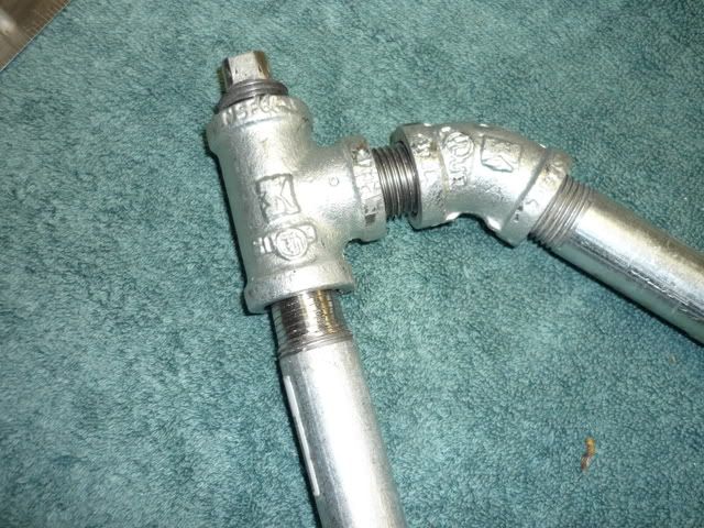
Start assembly with your "triangles." They are each made from 2 Ts, 2 45*
elbows, 1 90* elbow, 2 close nipples, 2 7" length of pipe, 1 8" length of
pipe. The 7" pipes are used for the legs of the triangle and the 8" pipe
is used for the diagonal side of the triangle. The close nipples are what
you use to attach the 45* elbows to the Ts. Just lay it all out and then
start putting it together tightening the joints as much as you can and
still keep them in the right orientation. Decide which T will be the
uppermost, the one with the small cap that fits into the indent on the
fork. You will make the union of that T with the 7" pipe that runs down
from the fork to the floor the last joint you fit together. (Terminology:
the vertical T is the one that is right below the fork when the bike is
lifted, it is more vertical than horizontal; the horizontal T is the one
that is flat on the ground when the lift is in position to be used. There
is only one 90* elbow on each triangle and it joins the two triangle legs
together. Other 90* elbows are used later to create the handle.)
On that length of 7" pipe use a grinder or a file and remove the last 1/2"
or so of the threads from one end. I used a grinder wheel and just turned
the pipe as the grinder ran and smoothed off the threads. It doesn't have
to be perfectly round and the thickness of the thread lines will be sort of
a guide if you are keeping the pipe more or less round. On the ones I did
I could still see dark lines around the end of the pipe where the threads
were, so I didn't need to go all the way down to zero threads. This
threadless end is the one that will fit in the uppermost T, the T that
holds the cap that goes into the indent on the fork.
Once you have all joints together for the triangle, except the last 7"
piece of pipe, twist the 90* elbow slightly out of its final orientation so
you can screw that last 7" piece (the one with the smooth end) into the
elbow. The threaded end goes into the 90* elbow, the smoothed end will go
into the T. A vise works well for attaching these joints and especially on
this one since you want that pipe as far into the 90* elbow as you can get
it. You want that because you will end up backing it out of the elbow
slightly once the smooth end is into the T. Now your triangle should lay
pretty flat on a table except that the 90* elbow with the 7" pipe will be
twisted out slightly.
Now, work with the T that will accept the end of the 7" pipe that has some
of the threads ground off. You want to turn that T in the direction of the
7" pipe's smooth end and then begin to work them so that they come
together. As you get them to their correct orientation where the smooth
end of the pipe is starting up the T they will begin to fit together. It
will be a pretty tight fit to bring them together but once the end of the
pipe is into the T you'll probably feel some play since you don't have a
treaded joint. Lay the triangle on a flat surface and see if you have all
the joints lined up so it does lay flat. Work the joints with pipe
wrenches if you need to to get them flat. As you work it flat you can also
back the 7" pipe out of the 90* elbow 1/4" or so. This drives the smooth
end of the pipe into the T further and still gives you a good joint since
you screwed it in to the 90* elbow as far as you could. I picked that
joint to be the threadless one b/c it will have mostly downward pressure
from the weight of the bike front. This seemed a better choice than the
diagonal part's joints since they really are there for stability I didn't
want to weaken them.
On my lift the triangles were the hardest part. A vise really helps. When
finished: The span between the two 45* elbows measures 7 1/8"; The span
between the horizontal T and the 90* elbow measures 6 1/4"; The span
between the vertical T and the 90* elbow measures about 6 1/8". This
should give you a good solid triangle that lays flat. You will need to
repeat this so you have two triangles.
Now it's time to drill holes in the 90* elbows to accept the garage door
hardware wheels and the bolts that are the axles for the wheels. The
pulley wheels I bought had a hole running through them and they came with a
bolt to go through that hole to use to mount the pulley wheels above your
garage doors. The bolt was not long enough to go through the wheel,
through the elbow and accept a flat washer, a split washer and a nut.
While you have your 3" pulley wheel garage door hardware in the store open
it up and remove one of the wheels from the package. Go to the bolts bin
and find a bolt of the right dimension and length. Having them a little
longer won't be a problem. The bolts I bought went through the hole in the
wheel and there was very slight play between the pulley/wheel and the bolt.
I think even a very tight fit would work because the wheel has a collar
around that hole that is on steel ball bearings according to the hardware
package. You should have your 90* elbow with you so you should be able to
measure just how long a bolt you will need fairly accurately.
With my triangles laying flat I used a file to slightly flatten the side of
the 90* elbow to help me mark it for the hole. I then measured up 3/4" and
over 3/4" and used a punch to mark an indent in the elbow. (I laid the
triangle flat on my work surface and used my tool box to create a plane,
slid the triangle up tight to the tool box then measured out form the tool
box 3/4" and marked the elbow. I rotated the triangle 90* and marked 3/4"
again on the elbow. Now I had a cross mark 3/4" in from each edge of the
elbow.)
My 3/8" drill bit slid through the hole in the wheel so that is what I
would use for the final holes through each elbow, but first I used a 1/8"
drill bit to do a pilot hole from the punch mark. I used the 1/8" hole as
a guide to line up my 3/8" bit and drilled through one side of the elbow.
I did this same procedure for the other triangle. I'd have used a
different method if I had a drill press but I don't. A buddy with a drill
press used my 3/8" bit and used the holes I had drilled as a guide and
completed the hole through the other side of each 90* elbow. This way the
two holes through each elbow are lined up square. After all this you will
have two pipe triangles and each will have a hole through it's 90* elbow to
accept the bolt and attach the wheel.
Before you attach the wheels work on the handle. Find your 12" pipes and
connect each to a 90* elbow. Attach the last 7" piece of pipe to one of
the elbows on a 12" pipe to make an L shape. You can now attach each to a
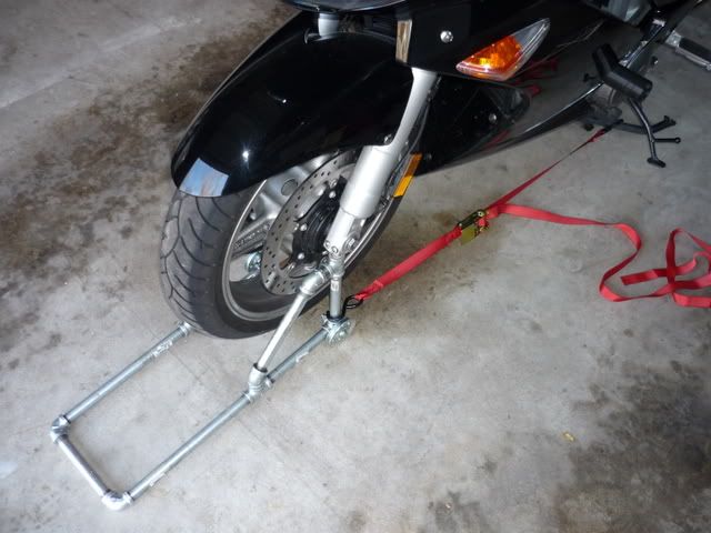
horizontal Ts on each triangle. I think if you look at the pictures you'll
understand. The 12" pipes, the two elbows and the 7" pipe will create a U
shaped handle when it is finally assembled. Once this is done you will be
done with your vise and can attach the wheels. I put my wheels on the
outside of the pipe to add a bit of side-to-side stability to the lift.
Using the outside gives the base about 2-3" more width and that much more
stability. Now you are ready to attach the two triangles together at the
end of the handles. This is sort of clumsy but easy. You just get the
side with the 7" pipe part of the handle threaded onto the side with the
90*elbow and swing them around until they are fully joined. You will need
some room to work to spin them around and around until they are joined.
Once joined you are almost done.
The 1/2" cap pieces thread into the vertical Ts and will go into the
indents in the bottom of each fork. The caps I bought had a square nub on
the end that is used to tighten them into the pipe you are capping off.
The square end didn't seem to fit really well into the fork indent so I
used my grinder and knocked the edges of the square off on each one. I
didn't round them, just took the edges off. Once that is done you can
screw the caps a few threads into the Ts and you are ready to lift.
The fork indents are about 8" on center. When you line your lift up on the
floor in front of the front wheel see of your caps are also 8" on center.
You should be able to twist them a bit and get them to fit into the forks
with no trouble. Once the nubs are into the fork indents (your bike should
already be up on the center stand) just push down on the handle and the
wheels roll back and the bike lifts up. It doesn't take much pressure to
lift it. In my case the clearance between the front tire and the garage
floor was about 1/2". I also experimented and slid two pieces of 3/4"
plywood under the wheels, one piece for each wheel, to give it more height.
It worked easily and was stable.
Other notes: 1) I tend to over build and since I don't know how much
rocking and force is needed to remove a front wheel I plan to use a tie
down strap from the back of the lift (the upright/vertical part just above
a wheel) to the center stand. That keeps the lift from rolling forward and
also keeps tension on the center stand. Maybe overkill but until I do my
first wheel removal I won't really know; 2) There is enough clearance in
front of the lift's wheels to slide a bar or another piece of pipe
perpendicular to the lift and the bike. This could be drilled and fitted
with eye-bolts to accept tie down straps from the bike down to provide more
stability side-to-side. Again, probably overkill and I'll probably not do
that unless it seems necessary during the removal process. 3) I'll
probably use some JB weld inside the joint (just remove the cap and pack
some in there) where the threadless pipe fits into the vertical T as a
precaution. When I used the lift there didn't seem to be a need but like I
said, I tend to over build.