Tree Doc
Well-known member
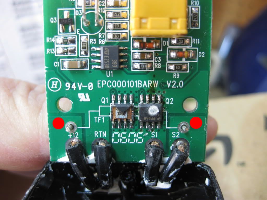
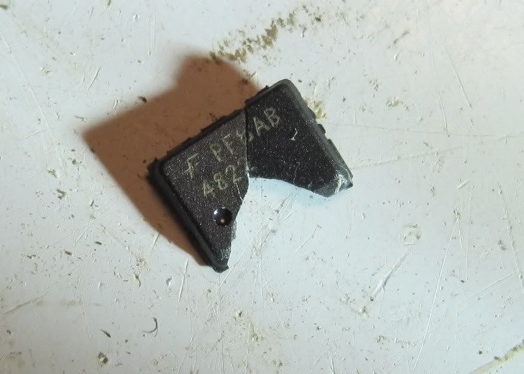
I think I cooked my single contoller. :glare: I was trouble shooting what turned out to be a bad co-ax plug on a Gerbings extension wire from controller to jacket. While working with my multi-tester, I got a little shaky with the probe and mistakenly crossed polarity. It blew a 15A fuse on my fuseblock which I replaced but now the controller no longer lights it's LED and no power comes through it. If I shake the contoller, I can hear something like a BB rolling around inside.
The housing has a joint where the front is mated to the back half but with a little experimental poking and prodding it doesn't appear that it willingly will come apart to reveal the chewy nougat center that I need to inspect.
Any of you electrical pros have a suggestion to get in or where to go from here?