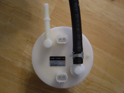
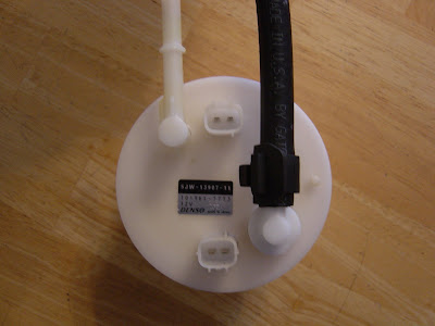
Installing a bulkhead fitting through the fuel pump

Yamaha FJR Motorcycle Forum

Help Support Yamaha FJR Motorcycle Forum:

This site may earn a commission from merchant affiliate links, including eBay, Amazon, and others.
Well, this does look slightly more encouraging with regard to having a relatively solid, leak free fitting.

Suspect you know you are not out of the woods yet.... ;) Let's see how the fuel line lays down and positioned, such that is isn't subject to pinching/occluded.

There won't be any pressure testing for me until the North thaws out again. But seriously, how could this not work?
Oh, there are ways.... there are always ways... :blink:

Still, this is more encouraging than earlier photos would suggest.

Watching this one, Joe.... B)

 
Last edited by a moderator:
There won't be any pressure testing for me until the North thaws out again.
Oh, there are ways.... there are always ways... :blink:
True. I woke up this morning thinking about a way to do it. It would involve making an airtight seal for the top of the tank. Then, I could do a leak down test using compressed air. I already have a tester that would work.

"I woke up this morning thinking about it." ... I must be getting old!

 
No, OLD is when you wake up thinking about something, then can't remember what it was!

Excellent project, fun to follow along as you're solving the many challenges...

Don

 
"I woke up this morning thinking about it." ... I must be getting old!
Yep, when all you can do is THINK about it, you ARE old! :unsure:

Be sure to fully pressurize the tank so we have a good test model and data. I think about 200 psi ought to do it! :blink:

Seriously, great work and read..

 
Great thread!!!! If this works which I think it will, is it possible to buy just this part of the Gen 1 fuel pump. I like this because I really didn't want to drill into the tank.

 
Nope, just want to add a cell.
I think the point is that this creative fix only works for Gen II owners. The reason is that on a Gen I, that extra nipple/line into the fuel pump body is already used as a return from the fuel rail to the tank in the Gen I fuel injection system. The Gen II's fuel injection system doesn't use a return line. Therefore, JTM is canabalizing a Gen I fuel pump body to use its return line nipple for the purpose of connecting the aux. fuel cell on a Gen II that doesn't need to use that nipple for the fuel return.


Question for the gurus: I guess if you wanted to get creative for a Gen I, you might run your return to a nipple on the aux. tank and then go ahead with what JTM has on the drawing board for your feed line from aux. tank to main tank. Any reason that wouldn't work (so long as the aux tank has a return nipple or (maybe) a Tee in the feed line)?

Interesting thread and project, JTM! Wishing you success on this very sanitary looking solution.

 
Last edited by a moderator:
Question for the gurus: I guess if you wanted to get creative for a Gen I, you might run your return to a nipple on the aux. tank and then go ahead with what JTM has on the drawing board for your feed line from aux. tank to main tank. Any reason that wouldn't work (so long as the aux tank has a return nipple or (maybe) a Tee in the feed line)?
IIRC, the return line is pressurized.

 
Very cool Joe, looks like you're making progress.

If you need heat for your garage I have a 110,000 BTU Kerosene torpedo type heater I'm not using that would keep you toasty. B)

Also, if you could use a extra set of hands (albeit uneducated ones :) ) let me know.

 
Last edited by a moderator:
Question for the gurus: I guess if you wanted to get creative for a Gen I, you might run your return to a nipple on the aux. tank and then go ahead with what JTM has on the drawing board for your feed line from aux. tank to main tank. Any reason that wouldn't work (so long as the aux tank has a return nipple or (maybe) a Tee in the feed line)?
IIRC, the return line is pressurized.
Yes, it is. But it could be done by teeing into the return line, with a shutoff valve isolating the line to the aux tank, and it could not be used while the bike was running.

 
If you need heat for your garage I have a 110,000 BTU Kerosene torpedo type heater I'm not using that would keep you toasty. B) Also, if you could use a extra set of hands (albeit uneducated ones :) ) let me know.
Sounds good. I'll call you when I'm getting ready to pressure test it. :download: Bring your helmet, and see if Wicked Webby will let you borrow a bullet proof vest. :grin:

 
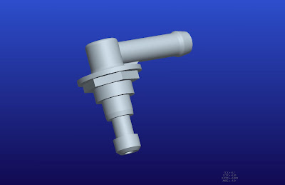
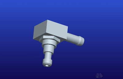
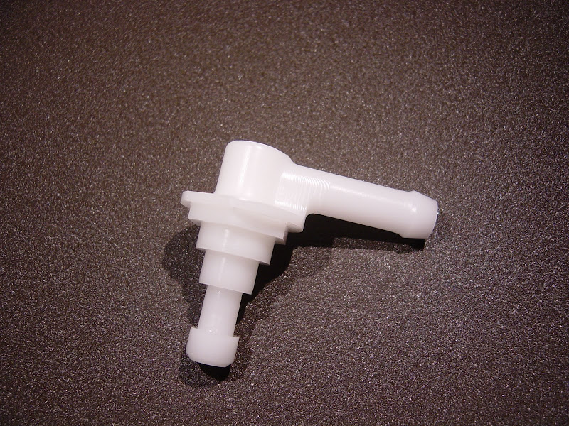
Here is the fitting I need to make. I rotated the hex 20 degrees on the model. The fuel line should drop right into the pocket in the heat shield.


Some of the features don't add anything to the fitting's function, so it could be simplified to this:


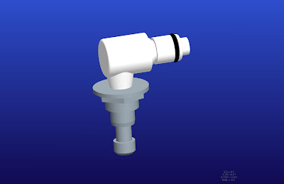
Now, this would be the razzle dazzle solution:


For those of you who yawn when you see a screen shot of a CAD model:


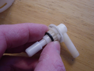
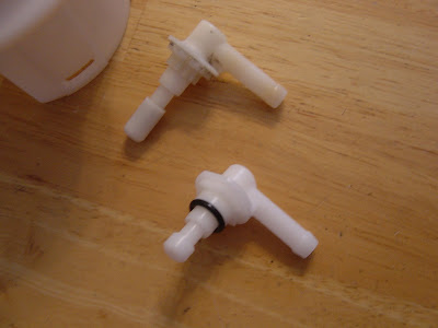
The new fitting is finished. Now I need to make a seal/ fitting for the tank's filler neck (for the pressure test).

 
Last edited by a moderator:
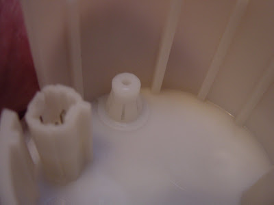
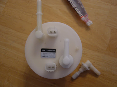
The parts store was open this morning, so I could get a little further with the install.

I decided to reuse the "O" ring:

DSC04379.JPG
[SIZE=36pt] [/SIZE]
DSC04381.JPG


DSC04383.JPG
[SIZE=36pt] [/SIZE]
DSC04384.JPG


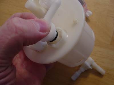
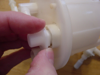
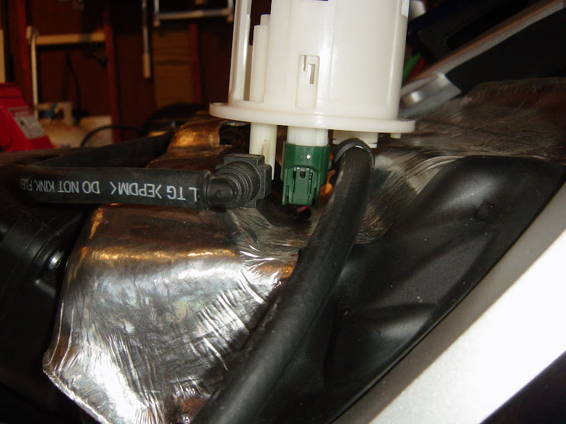
This is what It looked like right after I heard the satisfying "click" of the snap locks grabbing the new fitting:

DSC04385.JPG


Here a shot showing of the snap locks holding tight:

DSC04388.JPG


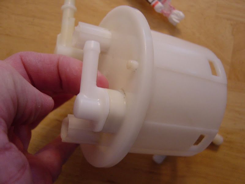
I looks like I got the orientation I was after:

DSC04389.JPG


DSC04391.JPG
[SIZE=36pt] [/SIZE]
DSC04392.JPG


Everything clears the heat shield now:

DSC04394.JPG


There is no reason this wouldn't seal as well as the original fitting. Do I really need to pressure test it?

 
So Joe when is your fuel pump modification kit going to come out? I will take one, thank you. :) Oh yeah I can also host a group buy for you. :lol: :lol:

 
Slick, absolutely slick.

As far as a pressure test, do it in the field.

What's the worst that could happen? :unsure:

 
Top