Gentlemen,
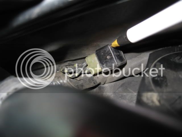
As promised I pulled my tank and had a look at my ground shunt located under the heat shield to the left and in front of the coolant pipe. To my relief it did not show any sign of overheating other than a slight yellowing like any other white connector would get in that spot above the engine. I did not have any symptoms of failure, or weird electrical quirks, but in light of recent developments with other FJRs I took the time to have a look.
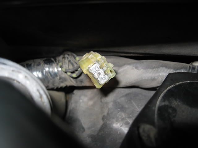
Here is the little bugger...
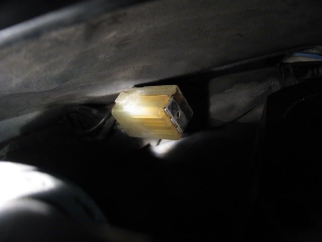
With the cap pulled the bridge looks clean...
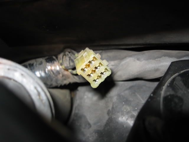
I pulled the bridge and the sockets look clean...
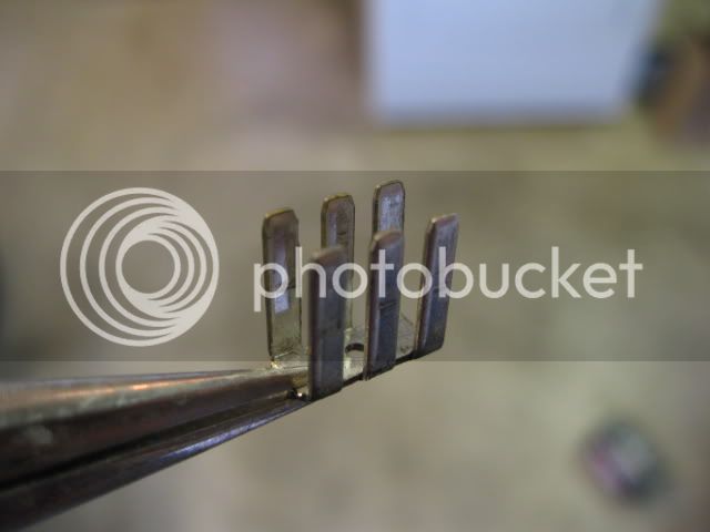
Here is the grounding bridge, again no sign of corrosion...
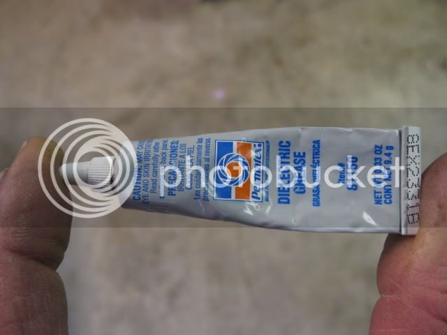
This is the dielectric grease available to me, I get it at my local Kragens/O'Rielly...
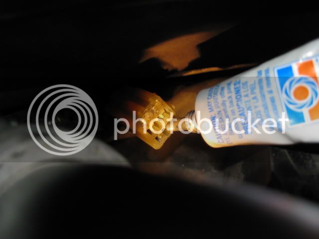
The nozzle is small enough I can inject grease into each socket...
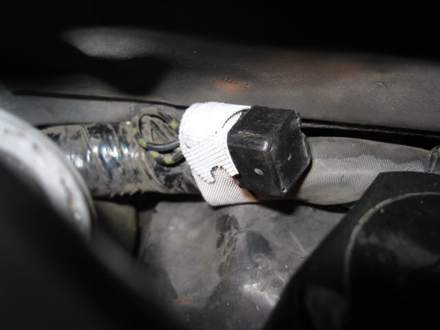
The bridge is now greased up and back in place...
The cap is back on and tied down with a light weight Velcro strap...
Please note that my bike has had an Ignition Relay Harness installed since last may - about a year.
So far so good!
I learned long ago with my Ascot that wire connectors are the major weak link to any motorcycle. When I brought my AE home from the dealer it took a couple of weeks for me to grease every connector I could find. I missed this one, fortunately for me it behaved itself.
By the way, for those of you that bought my Ignition Relay Harness, I applied Dielectric grease to the 4 tabs on the relay and the bullet connector. If you haven't already done so, you may want to grease up the contacts in the white connectors.
Hope this helps someone.
")
Brodie