Main ECU Connector Contamination...

Yamaha FJR Motorcycle Forum

Help Support Yamaha FJR Motorcycle Forum:

This site may earn a commission from merchant affiliate links, including eBay, Amazon, and others.
08FJR,
Sorry to hear about your problems...how many miles on your bike and did you make any changes recently?

The GenII series has different Connector Issues that may be your problem as discussed here:

https://www.fjrforum.com/forum//index.php?s...13632&st=20

Hope this helps....
03HiYoSilver,

Thanks for the reply. I have almost 13k on the odo. The only change I've made is added a GPS. It's wired directly to the battery. I have it on my winter projects list to add a power block.

Thanks for the link. I'm not finished reading all of it yet but have seen at lease two of the ground plugs it talks about. The one under the tank was wedged in tight next to the valve cover the first time I lifted the tank so I relocated it. That's the first one I'm going to look at. I figure all that time riding next to the cover put a lot of heat on it.

I'll post what I find on the link you gave me.

Thaks again,

Steve

 
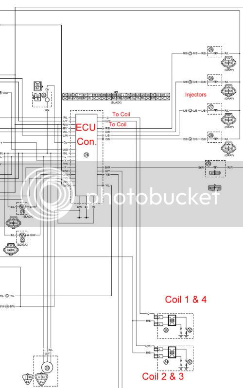
Added Main Harness Connector Wiring Diagram to post.

ConnMainHarnessPic.jpg


Last edited by a moderator:
Sorry for the resurrection, but I got here through a link in another thread. The wiring diagram you posted is NOT the connector you're describing. The one in the diagram is the ECU connector under the tool tray on the left side of the bike.

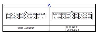
Your connector is wire harness connector A, which appears in the wiring diagram circuit as:

Connector%201.jpg


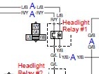
It's connectors appear in the circuit diagrams like:

Connector2.jpg


The letter 'A' means that's a connection in harness connector A. The diagram shows connectors A through something at the top, and actual connections are shown with the letter in the circuit lines where the connection occurs, and those connection are scattered all through the diagram.

(The Gen II wiring diagrams show the connectors in the actual diagram, which makes the connectors easier to find, but makes circuits harder to trace. It also makes the diagrams bulkier. I don't think the GenII diagrams actually show the famous ground spiders, though.)

 
Thanks WFooshe... at least it gives a general idea of the symbiotic nature between the hardware and the electronic connectors.

Hope you were successful with your oil leak... you should have garnered a honorary 5 Star Yamaha Service award with your excellent writeups & diagnosis.

 
I had one hard start adn a surging issue about a year ago. I cleaned and treated the connector with ACF 50 and the problem is now gone. I treat the connector about once a year when I have the bike down for major maintenance.

 
A couple of years back I opened up both connectors and found the dreaded corrosion there too. Cleaned it and silicone greased the connector up. Fast forward a couple of years to now . My '05 had started to surge a little excessively at idle recently, and remembering this post I dug it out to go over these connectors again and I'm a bit confused. I mean, I could definitely see how a corroded connector could be rersponsible for the engine not running right, but I can't see how these connectors would do it.

I went through all of the pins in these two connectors and traced them out to see if I could find something that makes sense. BTW, the below is specific to the 04/05 wiring harnesses. The '03 wiring and connectors appear to be similar, but a little different

The "A" connector has 11 pins:

Red/Yellow - Headlight Relay #1

Brown/White - Turn Signal Relay output

Green/Black - To Headlight Relay #2

Light green - to Neutral Indicator Light

Brown/Green - Turn Signal Relay input

Red/White - Instrument Panel power

Black2 - Instrument Panel ground

Yellow/Black - ECU trigger to Headlight Relay #2

Green/Yellow - ECU trigger to Radiator Fan Relay

Brown/Black - Power to Radiator Fan Relay

Blue - Power from Radiator fan relay to fan motor

The "B" connector has 10 pins

Sky blue/White - Control signal (neutral) to Accessory Box Relay

Brown - Power to Instrument Panel back-lights and Accessory box relay

Green/White - Fuel level sensor signal to INstrument Panel

Blue/Red - Power to front running lights

Dg - Power to right front turn signal and indicator

Chocolate - Power to left front turn signal and indicator

Black - Ground for front running lights, front turn signals and windshield drive

Sky blue - Down signal to windshield drive

Brown/Yellow - Power to windshield drive

Light green - Up signal to windshield drive

The Brown and Black wire shown in two different posts as having the most verdigris corrosion buildup goes to the radiator fan relay. :huh: That surely would not cause these kind of symptoms. I'm not saying cleaning these connectors didn't resolve some folks idle surging problems, but I sure the heck can't see why it would. :blink:

Maybe just moving the entire harness around is wiggling something else up in the nose, that actually does have something to do with the engine management? :unsure:

 
Last edited by a moderator:
The problem you folks are having is that you are all riding Gen 1 relics and the electrons are made of wood.
tongue.gif


The problem you folks are having is that you are all riding Gen 1 relics and the electrons are made of wood.
tongue.gif
Gen II's whose electricals were designed by the Prince of Darkness and your gonna go there?!
As much as I'd like to, Bungie, I can NOT agree with you....

The ghost of Joseph Lucas was given a Gen II electrical system, and after inspecting it, decided it was too crude and substandard, even for him.

The folks over at Magneti Marelli, upon inspecting a Gen II harness, shook their collective heads and sighed "Fix It Again, Tony!"

 
...I went through all of the pins in these two connectors and traced them out to see if I could find something that makes sense. BTW, the below is specific to the 04/05 wiring harnesses. The '03 wiring and connectors appear to be similar, but a little different

The "A" connector has 11 pins:

Red/Yellow - Headlight Relay #1

Brown/White - Turn Signal Relay output

Green/Black - To Headlight Relay #2

Light green - to Neutral Indicator Light

Brown/Green - Turn Signal Relay input

Red/White - Instrument Panel power

Black2 - Instrument Panel ground

Yellow/Black - ECU trigger to Headlight Relay #2

Green/Yellow - ECU trigger to Radiator Fan Relay

Brown/Black - Power to Radiator Fan Relay

Blue - Power from Radiator fan relay to fan motor (Indicated on Diagram as "L")

...

The Brown and Black wire shown in two different posts as having the most verdigris corrosion buildup goes to the radiator fan relay. :huh: That surely would not cause these kind of symptoms. I'm not saying cleaning these connectors didn't resolve some folks idle surging problems, but I sure the heck can't see why it would. Maybe just moving the entire harness around is wiggling something else up in the nose, that actually does have something to do with the engine management?

Sure do understand what you are saying. I have a Colored Wiring Diagram and even it seems insufficient to show the proper tracing, specifically with the Brown/Black Wire, to Connector "A" which appears to be the Main Wire Harness Connector.

Perhaps this Bad Connection(s) to this Harness Connector causes some Electrical Interference to the ECU in some way that causes some imbalance of readings to other components that would cause these conditions.

All I know is Cleaning Up this Connector (Mainly "A") forward of the Triple Tree on GENI FJR's solves a great deal of Intermittent Problems.

 
Last edited by a moderator:
Fred,

Upon looking at the Brown/Black Wire (which appears to most subject to corrosion) on a wiring diagram, here is what it feeds:

From the Fan,

the Wire becomes RED

where it goes to the Ignition Switch/

Fuel Injection/

Fuel Injection Relay/

then becomes a Red/Blue? wire that feeds into the ECU.

Since this wire also seems to also pick up more power than the other wires and would be more subject to more Heat/Contraction/Expansion against the Aluminum Contacts.
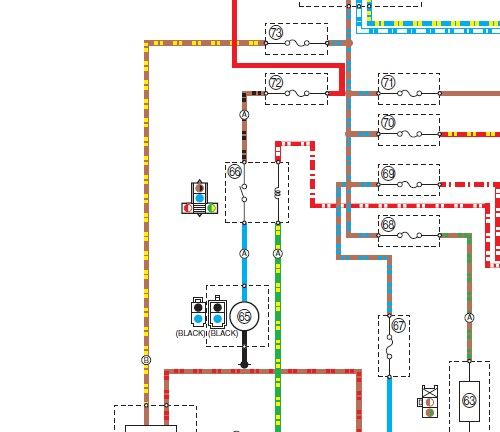
I think that you are reading the wiring diagram wrong, and going in the wrong direction. Here's the appropriate section of the diagram:

Fanwiring.jpg


The red wire on the right of fuse F-72 is the 12V supply coming from the battery, via the ignition switch. A bad connection "down stream" of that at the Fan relay connections (66) or the Fan motor (65) would not likely cause any issues on the 12V buss (red wire) going off to other things like the ECU.

 
I had very rare surging and running on 2 cylinders. Saw Code 34 3 times in 2006, 2 times on 2013 both were very short-lived faults and could not find it on trouble-shooting. Had it very bad today and almost got killed by it. Sure enough it caught error code 34 and was just running on 2 cylinders when I got home.

I found this topic and cleaning the connector fixed me right up.

Searching Error code 33 and Error code 34 should both to this topic. Fault code 33. Fault code 34.

I will also add intermittent ignition coil to the text to see if that helps with searching it out.

Thanks a lot!
punk.gif


I had lost the control of,the high beams and noted an intermittent connection when I wiggled the wiring. Opened mine up and everything looked clean but still shot it with CRC electrical cleaner which solved that problem. Not sure if coating those connections with grease is good or not.

 
I had lost the control of,the high beams and noted an intermittent connection when I wiggled the wiring. Opened mine up and everything looked clean but still shot it with CRC electrical cleaner which solved that problem. Not sure if coating those connections with grease is good or not.

My preference is to use ACF50 for all these connections. Never had a problem (of any sort), YMMV................

 
Top