Manual Cam Chain Adjuster

Yamaha FJR Motorcycle Forum

Help Support Yamaha FJR Motorcycle Forum:

This site may earn a commission from merchant affiliate links, including eBay, Amazon, and others.
There seems to be some interest in this so I will put it out there for folks to do what they want to with it. I have yet to install it because mine only has a few miles on the new one in it so I am waiting for snow fall before I get into it. I am certain it will work just fine.

cct006.jpg


This shows the stock cct disasembled and in order of assembly.
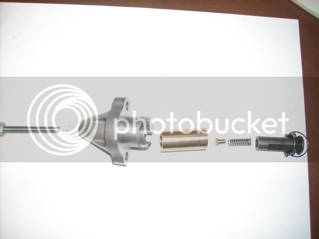
cct008.jpg


This shows the cct with the new parts in order of assembly.

cct010.jpg


This shows the parts that need to be made or purchased
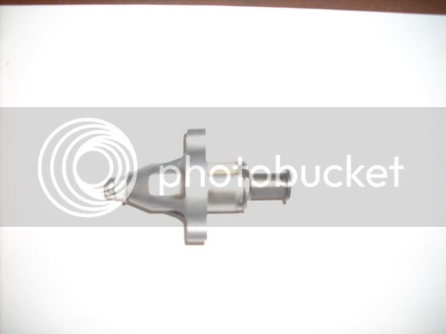
cct012.jpg


This shows it all together again.

The bushing that needs to be machined can be made out of most any material. I used bronze because I have lots from my boatyard days.

The OD is .711, the ID is .474 and the length is 1.460. All dimensions are +- .001

The spring came from Ace and is a .250 compression spring shortened to .750.

The small button goes in the end of the spring to servw as a base for the screw so it doesn't go into the spring. It is .250 on the big end and is .178 on the small end and is .330 long.

The screw is a standard 6mm x 55mm which is the same as the bolt in the end of the stock cct.

You need to run a 6mm tap through the cct body because the stock threads don't go all the way through. at this point clean up everything and get ready for assy.

I used some grease on the spring and button to keep them from falling out. Put the spring and button in the plunger from the cct. Assemble the plunger and the bushing into the cct housing and install the retainer clip. The original screw,sleve and spiral spring get discarded at this point.

The 6mm x 55mm screw along with the crush washer from the bolt go in the other end. Add a 6mm nut to the screw to act as a lock to hold adjustment.

Install in the engine as you would with the stock unit. If the screw is to long for assy then leave it out until the unit is installed and then put it in with a long screw driver.

For adjustment I would run the screw in until you feel a slight resistance and then go 1 turn to tension the spring. When I put mine in I will start the engine and slowly back out the adjuster until I get some noise and then in until it is quiet and then the 1 turn for tension.

I have no doubt that this will work just fine and require very little service.

If you want to wait until winter I will post up the results on mine.
Nice job FJRay! Personally I'd use a heavier grade screw or bolt (Allen head?) than the hardware store version which I think is kinda soft? Don't know what grade bolt the stock one is but I'd at least try and match that or I presonally would go up one grade higher as I live by the word "BulletProof"!
The screw is about a grade 5 so it is way stronger than the aluminum threads in the housing. The stock bolt is only a cork to fill the hole so strength is no issue. I agree a socket head would be nice but one was not avaliable at the time which means it wasn't in my bolt bin.
Let me see if I've got this figured out correctly, the spring in your set-up holds the plunger against the CC and the long screw takes up the slack. The brass/bronze plug in your set-up is being used for the adj. screw end to ride against while the other end fits the spring ID. I would think that the brass/bronze plug would be to soft and may contaminate the engine with brass/bronze shaving? If this is possible then wouldn't a steel plug work better or is this part of the plunger assembly isolated from getting into the engine as it's sealed from the engine by the bushing? But even if the soft shavings from the plug can't get into the engine they can still score or implant themselves into the bronze bore making the plunger assembly bore not as smooth which could result in the plunger assembly dragging or sticking in the bore? If I have this figured out correctly the adj. screw/bolt in your set-up would have some pressure on it from the spring? If so I'd still have at least a grade 3 screw/bolt to account for the spring pressure. This might be "overkill" but that's just me as I don't trust the hardware store garden variety screw hardness. I guess I'm a little confused as the heading for this thread said "Manual CC Adjuster" when in reality it's a modified manual/spring CC adjuster just like the stock unit?

After looking at the stock CCT pics it almost looks like a manual CCT with an adj. screw in the middle. So the thingy next to the housing must be a spring? So let me see if I've got this right? The stock CCT has an adj. screw that takes up all the free play in the CC and the spring then applies the correct pressure to keep the plunger seated against the CC loose spots? Also on the stock set-up I can see the small short screw that seals the hole for the CCT adj. screw mechanism. Just trying to understand the stock CCT and your up-graded one. No offense meant just trying to critique your set-up so if needed you can improve your design. And yes I've got the FSM just hadn't got around to the CCT yet.
I don't know if you have it figured or not allthough you mention it a number of times. The bronze ( big diff between brass and bronze ) is far more wear resistant than the rest of the aluminum engine. Thats why Bronze is used for bearings world wide and the bronze parts just sit there so there in nothing to create shavings. If you read the notes you will see that I used bronze because thats what I had. The bushing could be made out of plastic and work just as well as tool steel. The spring and the other bronze piece can be eliminated if you want. The purpose of the spring is to take up any change in tension as the chain rotates around the sprockets because all chain drives have tight and loose spots. After you look at the stock one you will understand why folks are having problems. The spring gets weak or breaks and there is nothing to keep it from backing off and letting the chain jump timing. In mine even if the spring broke it wouldn't back off enough to allow this. As far as the grade of the bolt you said you would prefer a grade 3 to a grade 5. In the bolt world the larger the number the harder the bolt so you seem to not have it figured out . No offense taken and critique all you want just figure it out first. Reengineer it any way you would like. :rolleyes:

 
Last edited by a moderator:
Good luck on this manual idea for a tensioner.... From my own history on manual tensioners (Yes a Yamaha)

I will stay with my automatic adjuster.

I'm just saying....

 
Now this thread is going somewhere.
I'm having fun counting how many times Ray's OP will be re-quoted in its entirety, along with all the pics and each successive reply.

Anybody here get in on the last snip tool group buy?
You mean....like this:

There seems to be some interest in this so I will put it out there for folks to do what they want to with it. I have yet to install it because mine only has a few miles on the new one in it so I am waiting for snow fall before I get into it. I am certain it will work just fine.
<snip the photos>

The bushing that needs to be machined can be made out of most any material. I used bronze because I have lots from my boatyard days.

<snip>

The screw is a standard 6mm x 55mm which is the same as the bolt in the end of the stock cct.

You need to run a 6mm tap through the cct body because the stock threads don't go all the way through. at this point clean up everything and get ready for assy.

<snip>

I have no doubt that this will work just fine and require very little service.

If you want to wait until winter I will post up the results on mine.
Or, Bob, it could be that some of those replying to this thread don't realize they DO NOT need to use the "reply icon that quotes the article when they could scroll another 1/2" down to the [SIZE=14pt]+[/SIZE] add reply icon and then type in their response or query.

Sometimes it's just a matter of familiarity of function rather than a "need" to quote the post to which they are responding.

:unsure:

;)

 
Last edited by a moderator:
FJRay said:

"I don't know if you have it figured or not allthough you mention it a number of times. The bronze ( big diff between brass and bronze ) is far more wear resistant than the rest of the aluminum engine. Thats why Bronze is used for bearings world wide and the bronze parts just sit there so there in nothing to create shavings. If you read the notes you will see that I used bronze because thats what I had. The bushing could be made out of plastic and work just as well as tool steel. The spring and the other bronze piece can be eliminated if you want. The purpose of the spring is to take up any change in tension as the chain rotates around the sprockets because all chain drives have tight and loose spots. After you look at the stock one you will understand why folks are having problems. The spring gets weak or breaks and there is nothing to keep it from backing off and letting the chain jump timing. In mine even if the spring broke it wouldn't back off enough to allow this. As far as the grade of the bolt you said you would prefer a grade 3 to a grade 5. In the bolt world the larger the number the harder the bolt so you seem to not have it figured out . No offense taken and critique all you want just figure it out first. Reengineer it any way you would like."

I know you said Bronze for the bushing, but you didn't say (unless I missed it) what material the piece was that was between the spring and screw end so I was guessing because of the color it was bronze or brass. So with the spring and screw end both riding on it, it could create bronze shavings which are not good no matter what your engine is made of. Any foreign material even if it's bronze shavings or even plastic shaving are NOT good for any engine! In any case IMHO it's to soft and a steel washer would work better. I also know the diff between grade 5 and grade 3 hardness, can we say Rockwell! You must have misunderstood what I was trying to say or I just said it wrong? I was saying that in this application grade 3 would be fine. Also bronze is used for bushings and not bearings! HD has been using them since like 1903 I think? No need to get an attitude, GEEZE! And this ISN"T a manual CCT if it has a spring in it to take up the slack. I'll just get the APE MANUAL CC adjuster unit and not have to worry about it.

 
Last edited by a moderator:
No need to get an attitude, GEEZE!
I didn't read attitude into Ray's post. You been drinkin' the Haterade?

And this ISN"T a manual CCT if it has a spring in it to take up the slack. I'll just get the APE MANUAL CC adjuster unit and not have to worry about it.
Cool.

Don't go away mad...

BTW, Nice snippage!
From WikipediA:

"An attitude is a hypothetical construct that represents an individual's degree of like or dislike for an item. Attitudes are generally positive or negative views of a person, place, thing, or event-- this is often referred to as the attitude object. People can also be conflicted or ambivalent toward an object, meaning that they simultaneously possess both positive and negative attitudes toward the item in question.

Attitudes are judgments. They develop on the ABC model (affect, behavior, and cognition). The affective response is an emotional response that expresses an individual's degree of preference for an entity. The behavioral intention is a verbal indication or typical behavioral tendency of an individual. The cognitive response is a cognitive evaluation of the entity that constitutes an individual's beliefs about the object. Most attitudes are the result of either direct experience or observational learning from the environment."

No hate here Toecutter, and I hardly ever get mad about anything especially on-line discussions.

 
Is this thread dead yet. Trying to argue on a forum is like trying to make sense to a drunk. :rolleyes:

 
Ray ~ Good on Ya, Mate for taking time and initiative to try to figure out a better solution for the hand grenade that has been designed in to our engines!

Your proposed solution is both elegant and simple... what's not to like about that?

If your prototype seems to work well, I'm sure a good source of nicities like allen head bolts, spec springs of the correct tension and strength, etc. could be readily found.

It would be very nice if we knew, or could measure the designed tension a fully functional stock CCT applies to the chain, so that force could be duplicated. Unfortunately, MammaYamma probably wouldn't share that bit of information with us.

Once again I applaud you for your efforts, and willingness to share! :clapping: :clapping: :clapping:

Don

 
It's not dead yet...

It would be very nice if we knew, or could measure the designed tension a fully functional stock CCT applies to the chain, so that force could be duplicated. Unfortunately, MammaYamma probably wouldn't share that bit of information with us.
Really no need for them to "share" anything other than selling one of us a new one. Vee haff der vays to reeferse enchineer it!

The ideal replacement tensioner would exert the same plunger force on the pivoting chain guide, but not allow itself to retract inadvertently. We know all too well what happens if a tensioner applies too little force, or allows the plunger to retract. But a tensioner that applies too much force could cause accelerated wear of the chain guides. I do not think the sprockets or chain would be adversely effected unless it was severe. A slack chain would be worse for wear on those parts.

How hard is it to measure / see / replace the chain guides? What happens in the event of a guide failure :unsure: Seems like something to be avoided.

Based on what I have seen of other people's CCTs (since I haven't had mine in my hands yet), the force exerted by the tensioner's plunger will be the torsional force of the releasing clockwork spring translated to thrust by the spiral groove of the CCT body. The amount of "tension" being exerted by a (released) stock CCT should be pretty low, and directly measure-able with a gauge. I'm guessing that the amount of the spring's force will vary (weaken) through the range of extension as the sping unwinds. So, knowing exactly what the nominal extension is would be handy, i.e. how far the plunger sticks out when new and at the "wear limit" of the chain. We'd probably have to translate a wear limit from other similar setups (or guess at one) because AFAIK Yamaha doesn't spec one.

Once we know the plunger force of the stock CCT, in addition to being a qualifying value for any other bike auto CCTs as potential transplant candidates, we could also reverse translate that to a "torque spec" for a manual CCT.

 
Last edited by a moderator:
I read somewhere that the amount of "wind" on the spring may vary depending on the limpness of the wrist of the guy that installed it..If the clock spring was not wound fully initially, then a new CCT would start off with weak pressure on the slipper shoe. True??

 
Well, ya can't just drop a bomb like than and then not explain. So what happened?
If you are refering to me no bomb.

But if you wish I will tell a short story. I had a XS 11 yamaha which had a manual cam adjustment. It had the piston mate up with the valves because the manual adjust screws(actually nut and bolt arangement) suddenly moved on start up and connected. That's the short story.

Fast forward to 2006 The FJR got noise after one of the valve checks and then after a short test ride it quieted down. My thoughts were that the cam chain adjust stuck. Before having the valves adjusted once sitting in my driveway it was very noise at start up so I turned it off, let it sit for a second, checked as much as I could, and then fired it back up. Noise was gone.

I went on the forum here and asked the question. Could OR should I change my cam chain adjuster.

I was told by some main members (admin) that you shouldn't have to change it at so low a distance ( 86,000kms).

They basically told me I was nuts to change a cam chain at such a low distance.

Not sorry I didn't take there advise ...well becasue of what I went through with the XS11.

Happy I did and it fact I may change it again at this valve check. (which should be around 178,000 )

As they say.... an ounce of prevention is worth a pound of cure.

So as I said before .... work on the idea of a manual cam chain adjuster.... all the power to ya... it's just not me.

 
I read somewhere that the amount of "wind" on the spring may vary depending on the limpness of the wrist of the guy that installed it..If the clock spring was not wound fully initially, then a new CCT would start off with weak pressure on the slipper shoe. True??
I'm one of those that has had several CCTs in my hands, and I'm one of the 2-3 that have observed the extreme non-linearity of spring force as well as unit to unit spring force variations.

I have posted where the operational part of the plunger spends most of its life and the rapid fall-off of spring force in that area. A healthy cam chain system has the CCT plunger start life almost half way extended. During the life of the CCT it extends less than a ¼ inch.

It is possible to add turns to the CCT spring giving it sufficient force to do its job. I've taken all the pictures that show how this can be done but didn't have time to complete a how-to before this manual adjuster thread started. The others that have had their CCTs apart have also noted that they can add more turns to the spring giving it proper force in the service length.

I hope the guys designing the manual adjuster have done a function and failure analysis so that they are producing a part with the correct extension, small service range and fine adjustability at the correct extension.

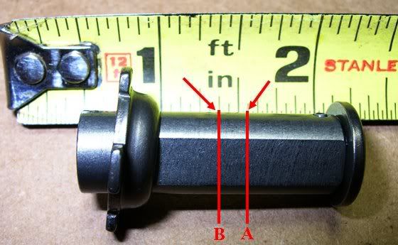
A is where most of the CCTs start life new, B is where spring force becomes too weak to do the job correctly. The spring force drops dramatically in the space between the two marks.

CCTPlunger8.jpg


Last edited by a moderator:
Maybe Yamaha could just modify the chain guide the tensioner pushes against? The guide could extend out a bit farther toward the tensioner plunger.

This would allow the spring to deliver more energy for the reduced plunger travel.

 
Maybe Yamaha could just modify the chain guide the tensioner pushes against? The guide could extend out a bit farther toward the tensioner plunger.
This would allow the spring to deliver more energy for the reduced plunger travel.
Why don't we just have them fix their crappy tensioner while we are asking for stuff?

 
But if you wish I will tell a short story. I had a XS 11 yamaha which had a manual cam adjustment. It had the piston mate up with the valves because the manual adjust screws(actually nut and bolt arangement) suddenly moved on start up and connected. That's the short story.
Assuming you are describing an adjustment screw/bolt/rod with locknut (and that's how I read it) then the only way the adjust screw could have moved is if the locknut wasn't tightened thoroughly/correctly. How is that the manual CCT's fault?

 
Top